AC Compressor — the pump that pressurizes the refrigerant
Condenser — the radiator-like unit in front of the engine radiator that cools the hot refrigerant gas
Receiver/Drier — a filter/dryer canister that removes moisture and debris (integrated into our replacement condenser)
O-rings — all seals at every refrigerant connection point (reusing old O-rings = guaranteed leaks)
Why Replace All At Once?
When an AC compressor fails, it often sends metal debris throughout the system. If you only replace the compressor, that debris will circulate and destroy the new one. Replacing the condenser and receiver/drier removes the main contamination points. Most compressor warranties also require replacement of the receiver/drier and O-rings.
SAFETY WARNINGS
Refrigerant: R-134a can cause frostbite on skin contact. When exposed to open flame or hot surfaces, it decomposes into toxic gases (phosgene). Always work in a well-ventilated area. Wear safety glasses and gloves.
Hot coolant: NEVER open the cooling system when the engine is hot. Pressurized coolant can spray and cause severe burns. Let the engine cool completely first.
Battery: Always disconnect the negative battery cable before working on AC components. The compressor clutch is electrically activated.
Vehicle support: If you jack up the car, ALWAYS use jack stands on solid frame points. Never work under a car supported only by a jack.
EPA Law: It is illegal to vent R-134a refrigerant into the atmosphere. Fines up to $44,539 per day per violation under the Clean Air Act. You must properly recover the refrigerant before opening any lines. See Section 3.5.
Key Specifications
Specification
Value
Refrigerant Type
R-134a
Refrigerant Charge Amount
480g (~16.9 oz) — verify on underhood sticker
Compressor Oil Type
PAG ISO 46 (FD46XG)
Total System Oil Capacity
120 ml (4.06 fl oz)
Drive Belt Type
Single serpentine belt with automatic tensioner (2.5L)
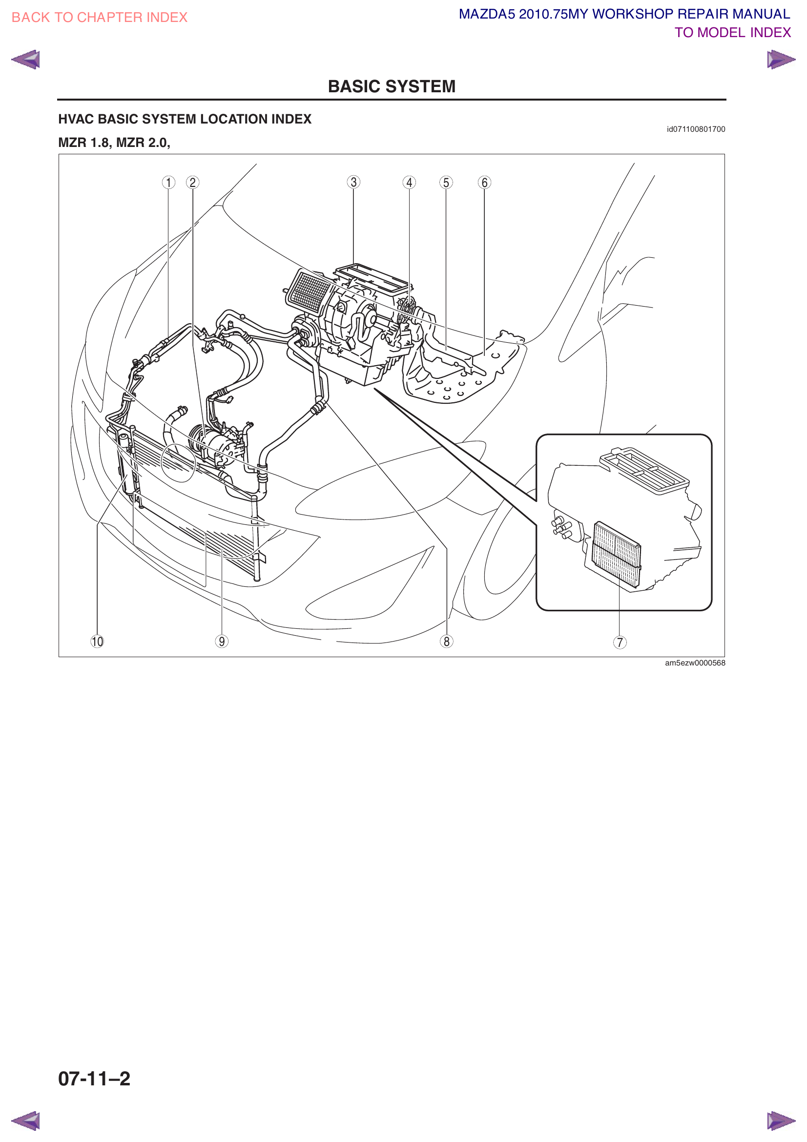
AC System Overview — Component LocationsAC System Component Details
Section 1 — Parts List
Order all parts before starting. Having everything on hand avoids leaving the system open to moisture while waiting for deliveries.
AC Compressor (2013 Mazda5 2.5L)HS18 type compressor — comes pre-oiledSearch Amazon
AC CondenserAluminum parallel-flow type; sits in front of radiatorSearch Amazon
Note: Our replacement condenser has the receiver/drier integrated (attached directly to the condenser). If yours is separate, you'll need to buy a standalone receiver/drier and follow the bumper removal steps in Section 8.
O-Ring Seal Kit (full AC system)Replace ALL o-rings at every connection. Never reuse old ones.Search Amazon
R-134a RefrigerantNeed 480g (~17 oz). Buy 2–3 cans of 12 oz each.Search Amazon
PAG 46 Compressor OilFD46XG compatible. For oil balancing procedure. Need at least 120ml.Search Amazon
Engine Coolant (FL22 type)~4L needed for top-up after draining radiator. Pre-mixed or concentrate+distilled water.Search Amazon
Serpentine Belt (optional — if worn)Good time to replace if cracked/glazed. 2013 Mazda5 2.5L.Search Amazon
Push-Pin Clip Assortment (Mazda)The plastic "Christmas tree" clips on the under cover, splash shield, and bumper are brittle and often snap during removal. Grab a bag of spares — they're cheap.Search Amazon
Pro Tip: Many vendors sell complete AC kits that bundle the compressor, condenser, receiver/drier, and O-ring kit at a discount. Search for "2013 Mazda 5 AC kit" on Amazon or RockAuto.
Search AC Kits on Amazon
Section 2 — Tools Required
AC-Specific Tools
AC Manifold Gauge SetWith R-134a quick-connect couplers. Blue=low side, Red=high side, Yellow=center service hose.Search Amazon
AC Recovery/Recycling MachineRequired to legally recover R-134a before opening lines. Many units (like the VEVOR) also include a built-in vacuum pump for evacuation, so you may not need a separate one. See Section 3.5.Search Amazon
Vacuum Pump (1/4 HP or larger)Only needed if your recovery machine does NOT have a built-in vacuum pump. Used to evacuate air and moisture before charging.Search Amazon
Digital Kitchen/Postal ScaleFor weighing refrigerant precisely by gram. Must charge by weight, NOT pressure.Search Amazon
Electronic AC Leak DetectorSniffs for refrigerant leaks at connections after charging.Search Amazon
Spring Lock Coupling Disconnect Tool SetIf your lines use spring-lock fittings (push-to-connect type), you need these to release them.Search Amazon
Vehicle Lifting
Floor Jack (2+ ton)For raising the front of the car. The Mazda5 front jack point is the front crossmember.Search Amazon
Jack Stands (pair, 2+ ton)Place on the front pinch welds (reinforced seams along the underside of the car, behind each front wheel).Search Amazon
Wheel ChocksPlace behind rear wheels before jacking.Search Amazon
Breaker bar or long ratchet + 15mm or 19mm socket (for the serpentine belt tensioner)
Trim removal tools / plastic pry bars (for clips and push-pins)
Miscellaneous
Drain pans (2) — one for coolant, one for compressor oil
Caps/plugs for open refrigerant fittings (or clean rags + zip ties as temporary seals)
Clean measuring cup (for compressor oil transfer)
Paper towels / shop rags
Permanent marker / masking tape (for labeling connectors and hoses)
Phone/camera (take photos before disassembly!)
2.5L Engine Note: The 2013 Mazda5 with the 2.5L engine uses a single serpentine belt with an automatic spring-loaded tensioner. You do NOT need the special Mazda SST stretch-belt tools (49 B015 102, 103, 104) — those are only for the MZR 2.0L engine. A simple breaker bar and socket is all you need for belt removal/installation.
Section 3 — Preparation
Park on a flat, level surface — concrete driveway or garage floor is ideal. Avoid gravel, grass, or slopes.
Engage the parking brake and place wheel chocks behind both rear wheels.
Let the engine cool completely — ideally let the car sit for 2+ hours, or overnight. You'll be draining coolant and don't want to get burned.
Disconnect the negative battery cable using a 10mm wrench. The negative terminal is marked with a “−” symbol and typically has a black cable. Tuck the cable away so it can't accidentally touch the terminal. Wait at least 1 minute before proceeding.
Gather all parts and tools — lay them out organized. Nothing worse than realizing you're missing a part with everything disassembled.
Take photos of everything before you start removing anything:
Serpentine belt routing (there may also be a sticker diagram in the engine bay)
All hose and connector locations
Wiring harness routing
AC line connections
Bumper fastener locations
Pro Tip: Label every connector, hose, and bolt location with masking tape and a marker as you go. It makes reassembly much less stressful, especially if this job spans multiple days.
Section 3.5 — Refrigerant Recovery (DIY)
Before you can open any refrigerant line, you must first recover all the R-134a from the system. Venting refrigerant to the atmosphere is illegal and carries severe fines.
What You Need: AC Recovery Machine (~$300–500)
A recovery machine is a self-contained unit with its own compressor, storage tank, filter, and gauges. It pumps refrigerant out of your car's AC system and stores it for reuse or recycling. This is the standard way to do it — straightforward, reliable, and fast.
VEVOR AC Recovery Machine (R134a/R1234yf)Fully automatic with built-in tank, scale, and filter. The most popular DIY option.Search Amazon
Other brands: Robinair, YellowJacket, Mastercool (~$200–400 for recovery-only units).
Alternative: Check local tool rental shops, or buy a used unit on eBay/Facebook Marketplace.
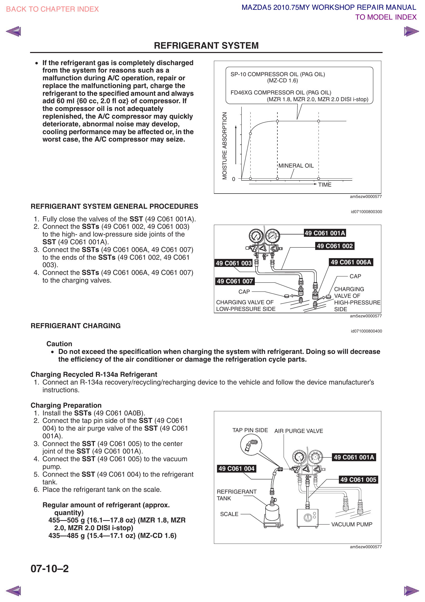
Understanding Your Manifold Gauge Set
If this is your first time using manifold gauges, here's what you're looking at:
Blue gauge (left) — reads low-side pressure. The scale goes from vacuum (below 0) up to ~120 psi. During normal AC operation, this reads 25–45 psi.
Red gauge (right) — reads high-side pressure. The scale goes up to ~500 psi. During normal operation, this reads 150–250 psi.
Blue hose — connects to the low-pressure service port on the car (larger fitting, usually near the firewall on the suction line, often has a blue or black cap).
Red hose — connects to the high-pressure service port on the car (smaller fitting, usually near the condenser at the front, often has a red cap).
Yellow hose (center) — connects to the service equipment: the recovery machine, vacuum pump, or refrigerant can depending on the step.
Blue valve knob (left) — opens/closes the path between the low-side hose and the center hose.
Red valve knob (right) — opens/closes the path between the high-side hose and the center hose.
Key concept: The gauges always show pressure regardless of whether the valves are open or closed. The valves only control whether refrigerant can flow through the center hose. So you can monitor both pressures with both valves closed.
Locating the Service Ports
Open the hood and look for two small metal tubes with threaded caps, each about the size of a tire valve stem.
Low-side port: On the larger-diameter suction line, typically near the firewall (back of engine bay) on the passenger side. The quick-connect coupler on your blue hose will only fit this port.
High-side port: On the smaller-diameter discharge line, typically near the condenser (front of engine bay). The quick-connect coupler on your red hose will only fit this port.
The fittings are different sizes on purpose — you physically cannot connect the wrong hose to the wrong port.
Remove the protective caps from both service ports.
Connect the blue hose to the low-side port — pull back the collar on the quick-connect coupler, push it onto the port, then release the collar. It should click and lock on.
Connect the red hose to the high-side port — same procedure.
Connect the yellow (center) hose to the recovery machine's inlet fitting.
Before opening any valves, read both gauges. A working system will show some static pressure (typically 70–100 psi on both sides when the engine is off and temperatures are moderate). If both gauges read 0, the system is already empty.
Open both manifold valves (turn the blue and red knobs counterclockwise).
Turn on the recovery machine — it will pull refrigerant out of the vehicle through both ports and store it in its internal tank.
Let it run until the machine auto-shuts off (system pressure reaches ~0 psi or a slight vacuum).
Close both manifold valves. Wait 5 minutes, then check if the pressure rises on your gauges. If it rises above 0 psi, open the valves and run the machine again — some refrigerant was trapped in the oil/lines and is slowly releasing.
Repeat until pressure holds steady at 0 psi for 5 minutes.
Close both valves and turn off the machine. Leave the hoses connected if you're proceeding with work immediately, or disconnect and cap the ports.
After recovery: Note how much refrigerant was recovered (most machines display this). If significantly less than 480g came out, the system may have already had a leak — good to know for later diagnosis.
Pro Tip: Many of these machines (especially the VEVOR units) can also handle the evacuation and charging steps later in Section 11, so the machine pays for itself across the whole job.
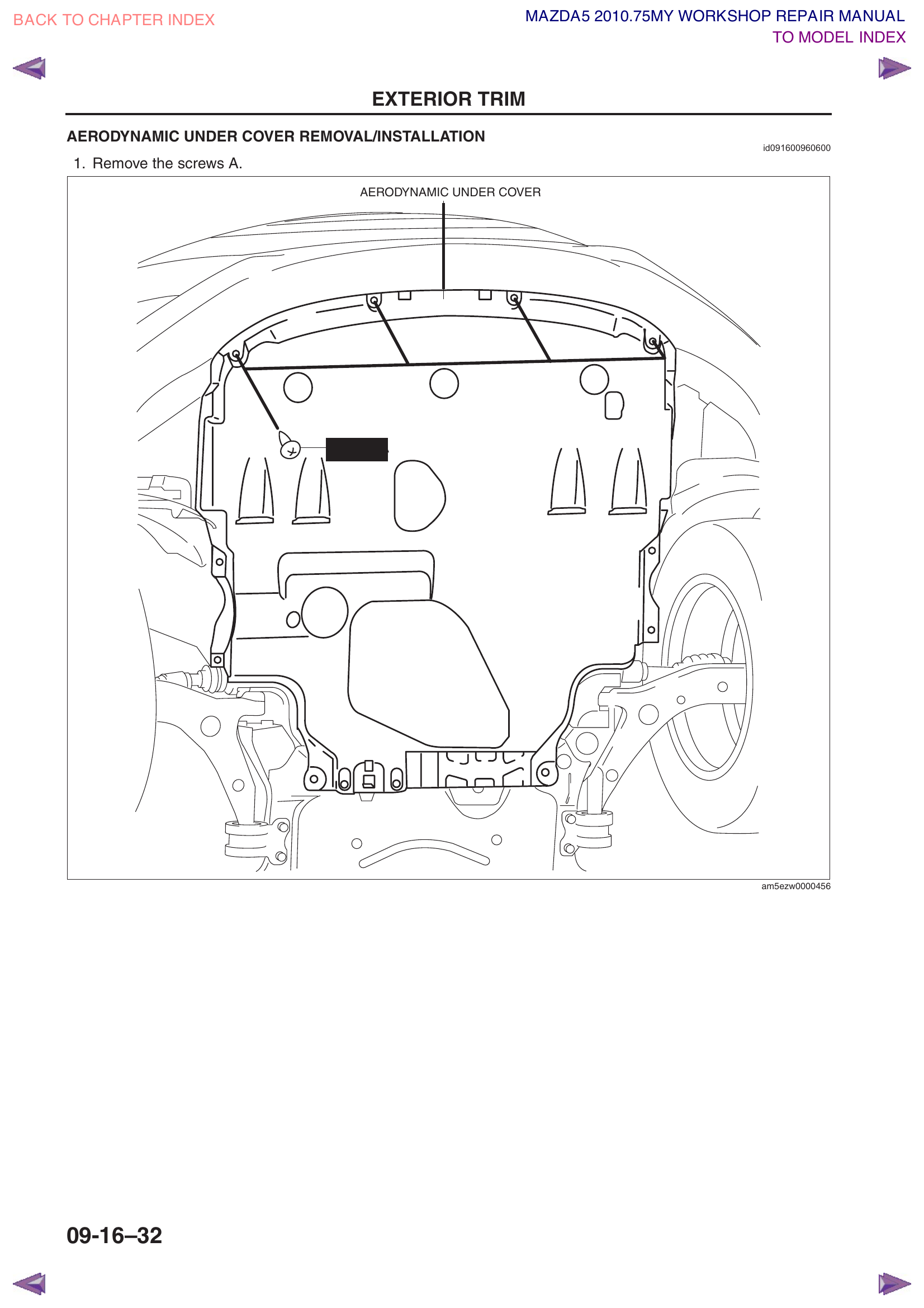
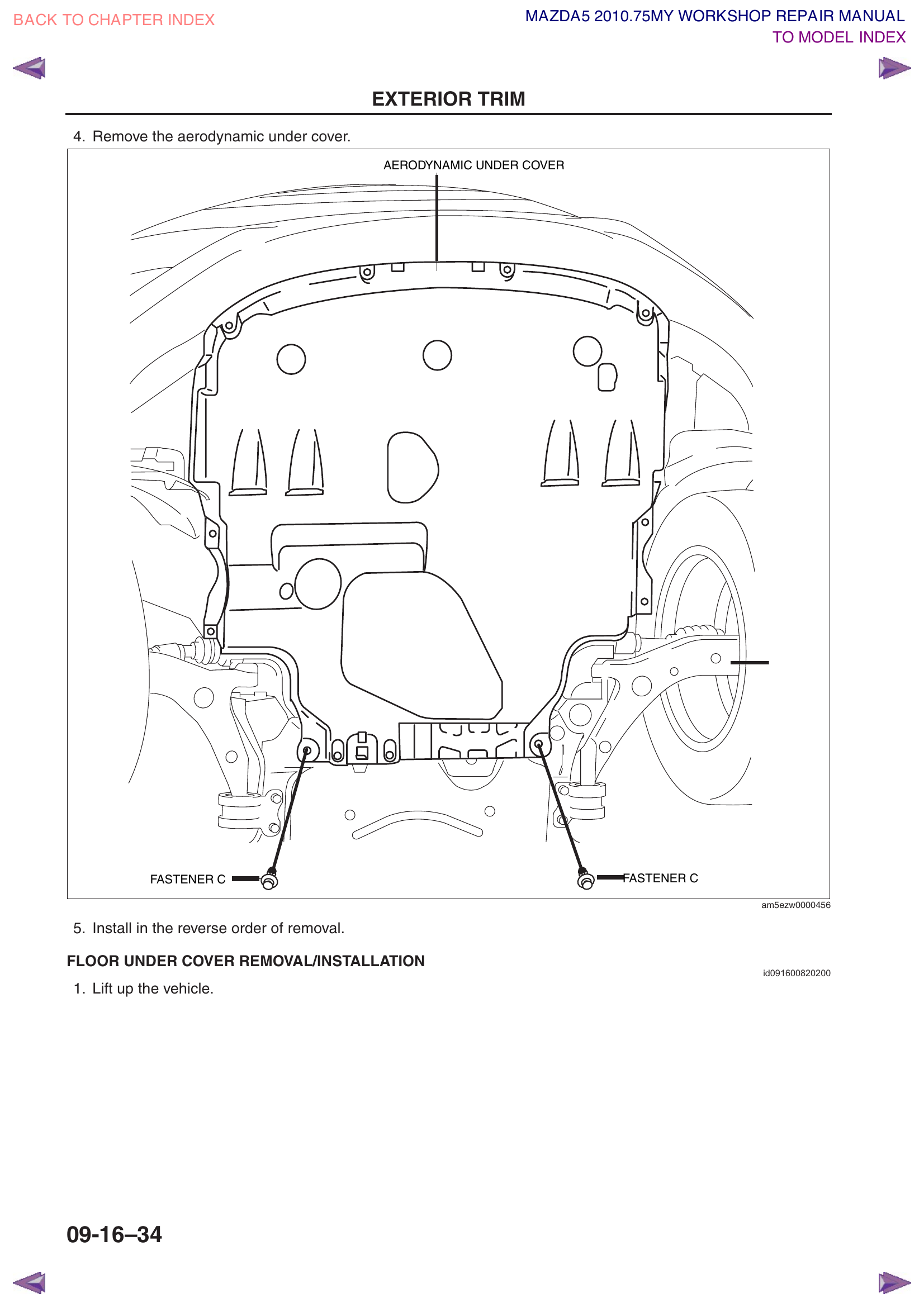
Section 4 — Remove Aerodynamic Under Cover
Workshop Manual Reference: 09-16-32
The aerodynamic under cover is the large plastic shield that covers the underside of the engine bay. It must be removed to access the compressor from below.
Raising the Vehicle
You need to get under the front of the car. You have two options:
Option 1: Drive-on ramps — easiest if you have them. Drive front wheels up, set parking brake, chock rear wheels.
Option 2: Floor jack + jack stands:
Place wheel chocks behind both rear wheels.
Position the floor jack under the front crossmember (the large metal beam running left-to-right behind the front bumper).
Jack up the front of the car until you have comfortable working space underneath (~12–18 inches).
Place jack stands under the front pinch welds (the reinforced seam running along the bottom edge of the body, just behind each front wheel). The owner's manual shows these locations.
Lower the car onto the jack stands. Wiggle the car to confirm it's stable before getting underneath.
NEVER work under a car supported only by a floor jack. Jacks can fail. Always use jack stands.
Under Cover Removal Steps
Remove screws A — multiple small Phillips-head screws along the front edge of the cover.
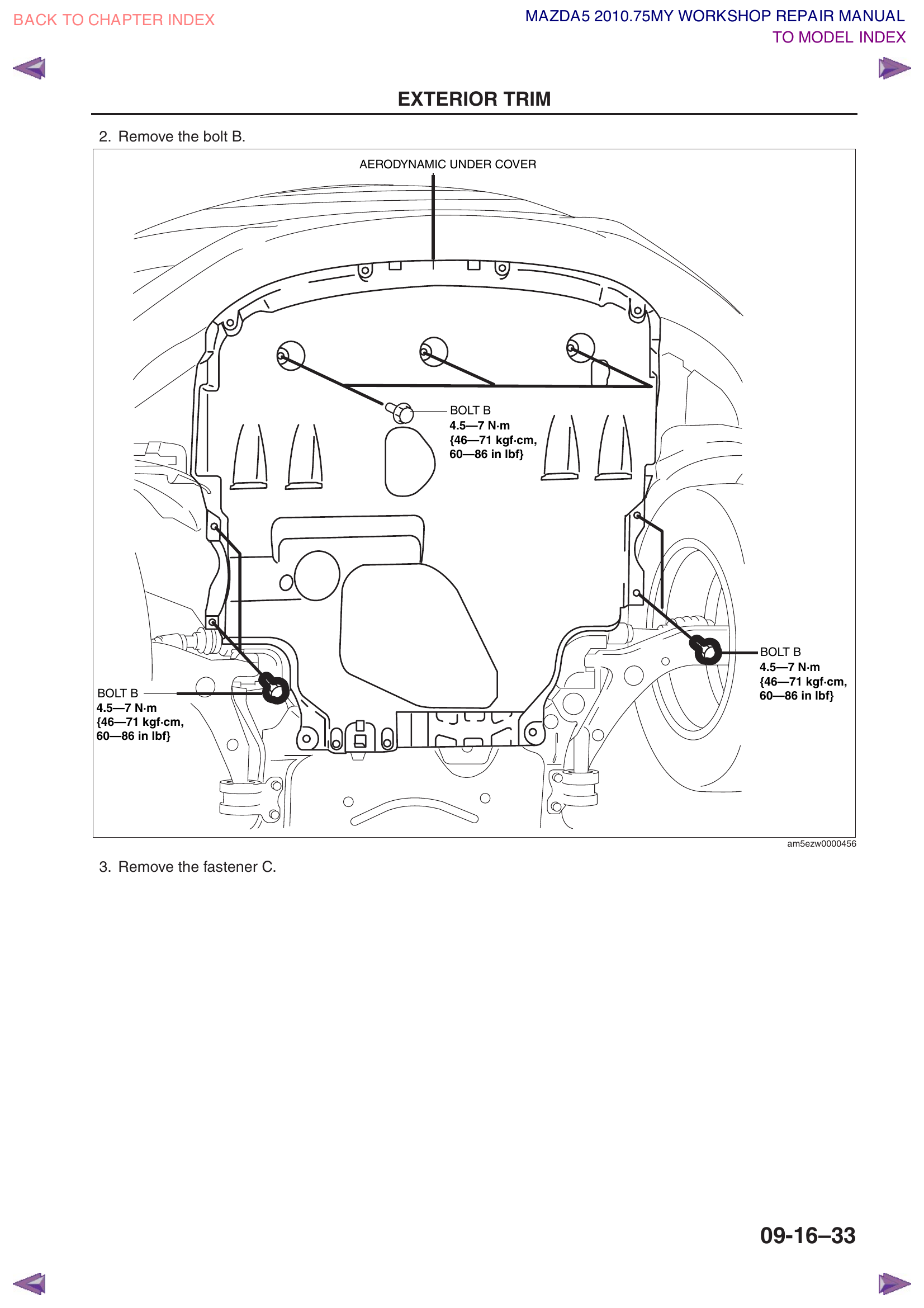
Remove bolts B — 3 bolts (torque spec: 4.5–7 Nm / 40–62 in-lbf). Use a 10mm socket.
Remove fasteners C — these are push-pin clips (also called "Christmas tree clips"). To remove them:
Use a trim removal tool or flathead screwdriver
Pry up the center pin first (it pops up about 3mm)
Then pull the entire clip out
Be gentle — these clips are reusable but break easily
Pull the under cover straight down and set it aside.
Step 1: Remove screws AStep 2: Remove bolts B (4.5–7 Nm)Steps 3–4: Remove fasteners C & pull down
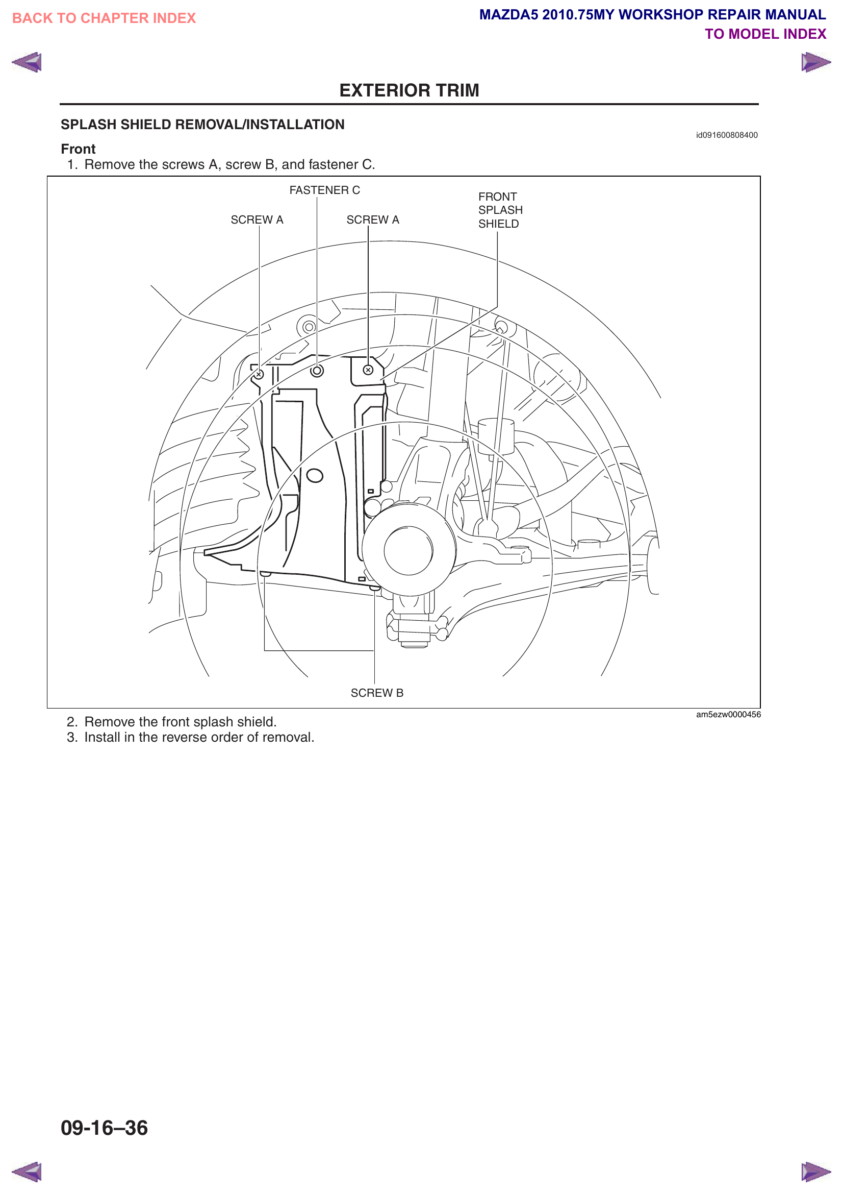
Section 5 — Remove Splash Shield
Workshop Manual Reference: 09-16-36
The front splash shields are the plastic panels inside each front wheel well. You may need to remove them (or at least fold them back) for better access to the compressor and condenser area.
Turn the steering wheel to one side to expose the inner fender area.
Remove screws A, screw B, and fastener C — as shown in the diagram.
Pull the splash shield free and set aside.
Repeat on the other side if needed.
Front splash shield — Screw A (top, 2 locations), Screw B (bottom), Fastener C (top center) all labeled
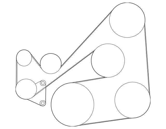
The 2.5L engine uses a single serpentine belt that drives everything: alternator, AC compressor, water pump, and idler pulleys. It has an automatic spring-loaded tensioner — no manual tension adjustment needed. To remove the belt, you simply release the tensioner.
Note on the workshop manual: The manual pages for the MZR 1.8/2.0 engine reference "SST" tools (Special Service Tools — Mazda proprietary jigs like 49 B015 102/103/104). Those are for the 2.0L's stretch-fit A/C belt and do NOT apply to the 2.5L. Your engine uses a standard serpentine belt with an auto-tensioner — no special tools needed.
Before touching the belt, photograph the belt routing. There may be a routing diagram on a sticker in the engine bay (radiator support or underside of the hood). If not, use the diagram below and photograph yours from the front of the engine for reference.
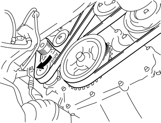
Locate the automatic belt tensioner (#1 in the diagram below) — it's a small pulley on a spring-loaded arm, lower-left area of the belt system.
Place a 14mm socket on a breaker bar or long-handle ratchet on the tensioner center bolt.
Rotate the tensioner clockwise (toward the front of the car) to release tension on the belt. The tensioner arm will compress against its spring.
While holding the tensioner back, slip the belt off the easiest pulley (the tensioner pulley itself or an idler).
Slowly release the tensioner arm.
Remove the belt completely.
Pro Tip: If you're replacing the belt (recommended if it shows cracks, glazing, or fraying), just cut the old one off — it makes removal much easier and you won't need it again.
Serpentine belt routing — 2012–2015 Mazda5 2.5L. See pulley legend below. Source: mazdas247.comTensioner release — rotate clockwise (toward front of car) with a 14mm socket to release belt tension. From Mazda factory service manual.
Pulley Legend (viewing the engine from the passenger side, front of car to the right): Top-right (largest): Alternator/Generator Center (large): Water pump Bottom-center (largest): Crankshaft pulley Bottom-right (large): A/C compressor clutch Bottom-left (with bolt detail): Auto tensioner — 14mm center bolt Left (small): Idler pulley (smooth) Upper-left (small): Idler pulley (grooved)
The Mazda5 has NO belt-driven power steering pump — it uses an electric EHPAS system. Diagrams from the Mazda3 2.5L showing a "P/S pump pulley" do not apply.
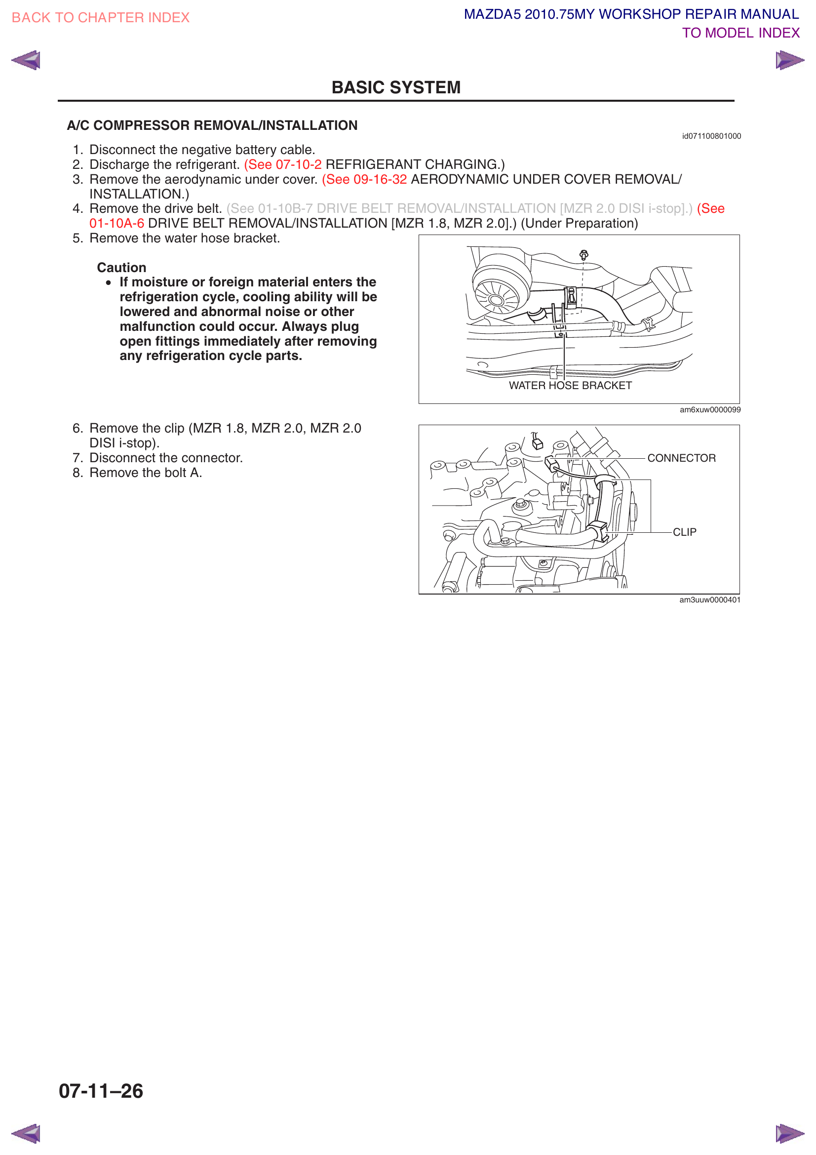
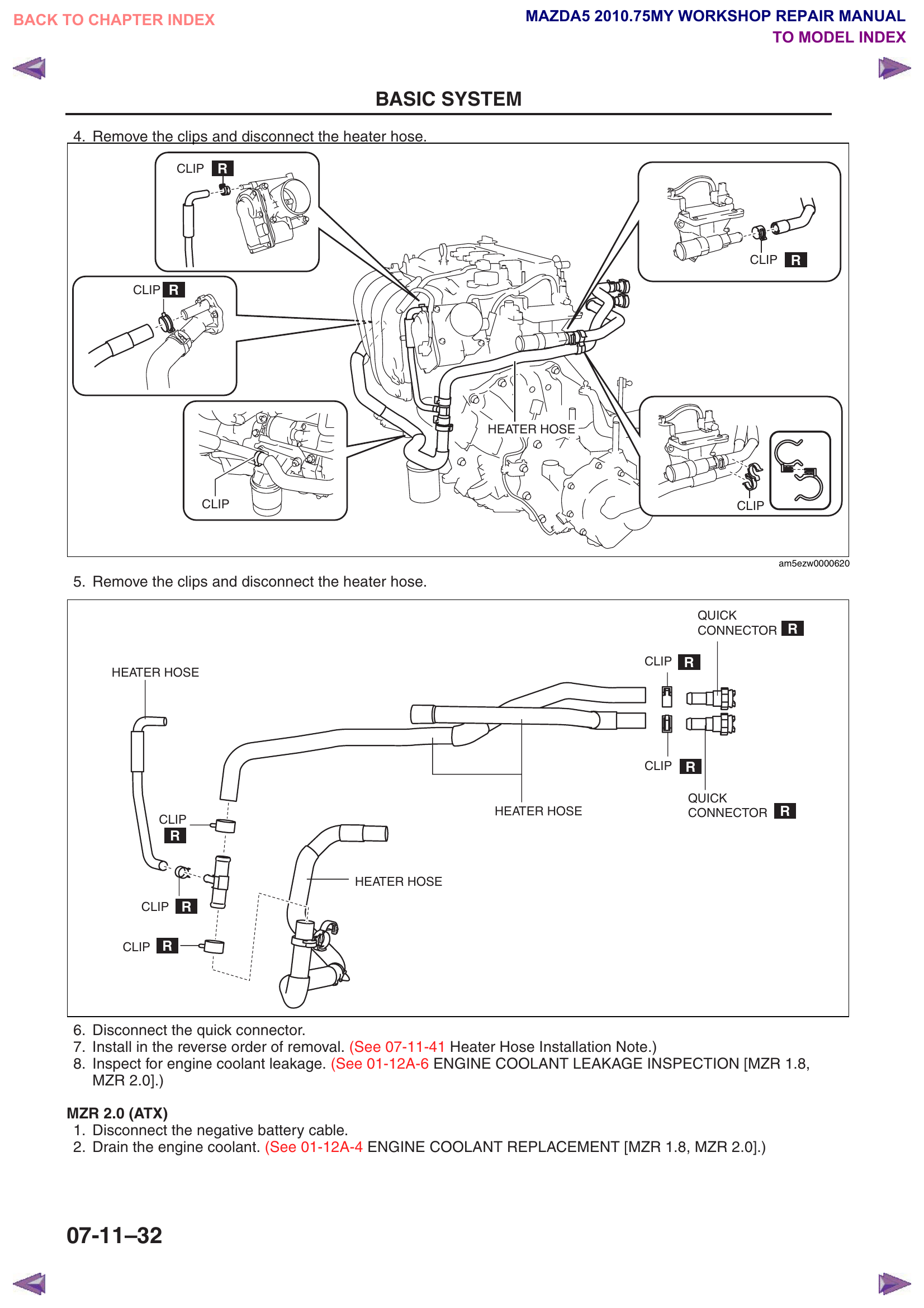
There's a bracket near the compressor that holds a coolant/water hose in place. Remove the bolt holding this bracket to move the hose out of the way. Simple bolt removal — just moves things aside for clearance.
Locate the wire harness clip on the compressor. It's a small retaining clip that holds the wiring harness in place.
Remove the clip (squeeze or pry with a small screwdriver).
Disconnect the electrical connector: press the locking tab on the connector and pull it straight off. Don't yank on the wires.
Water hose bracket, connector, and clip locations on compressor
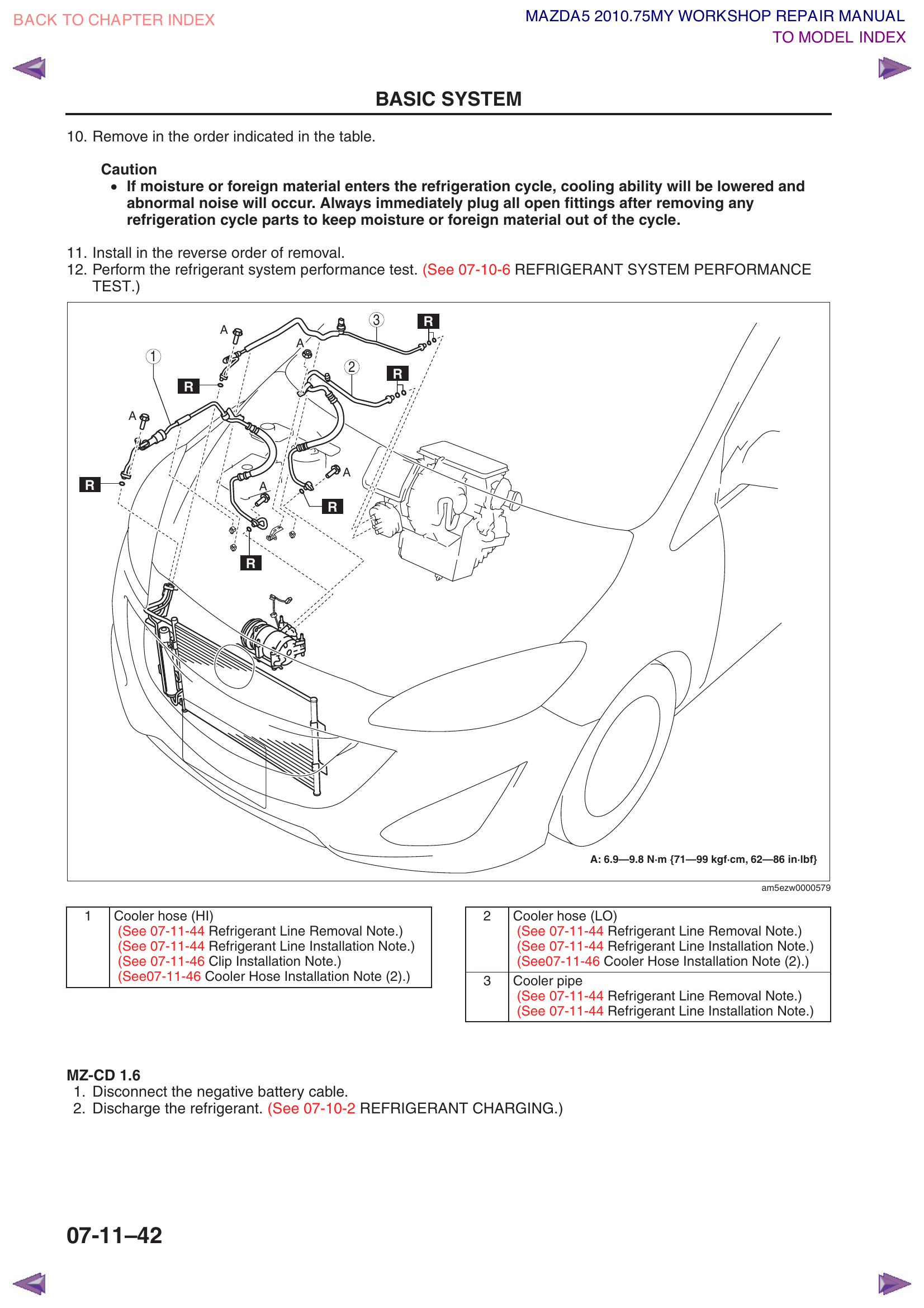
Step 6d — Disconnect Refrigerant Lines
There are two refrigerant lines connected to the compressor:
Cooler hose (HI) — the high-pressure discharge line (smaller diameter, hot during operation)
Cooler hose (LO) — the low-pressure suction line (larger diameter)
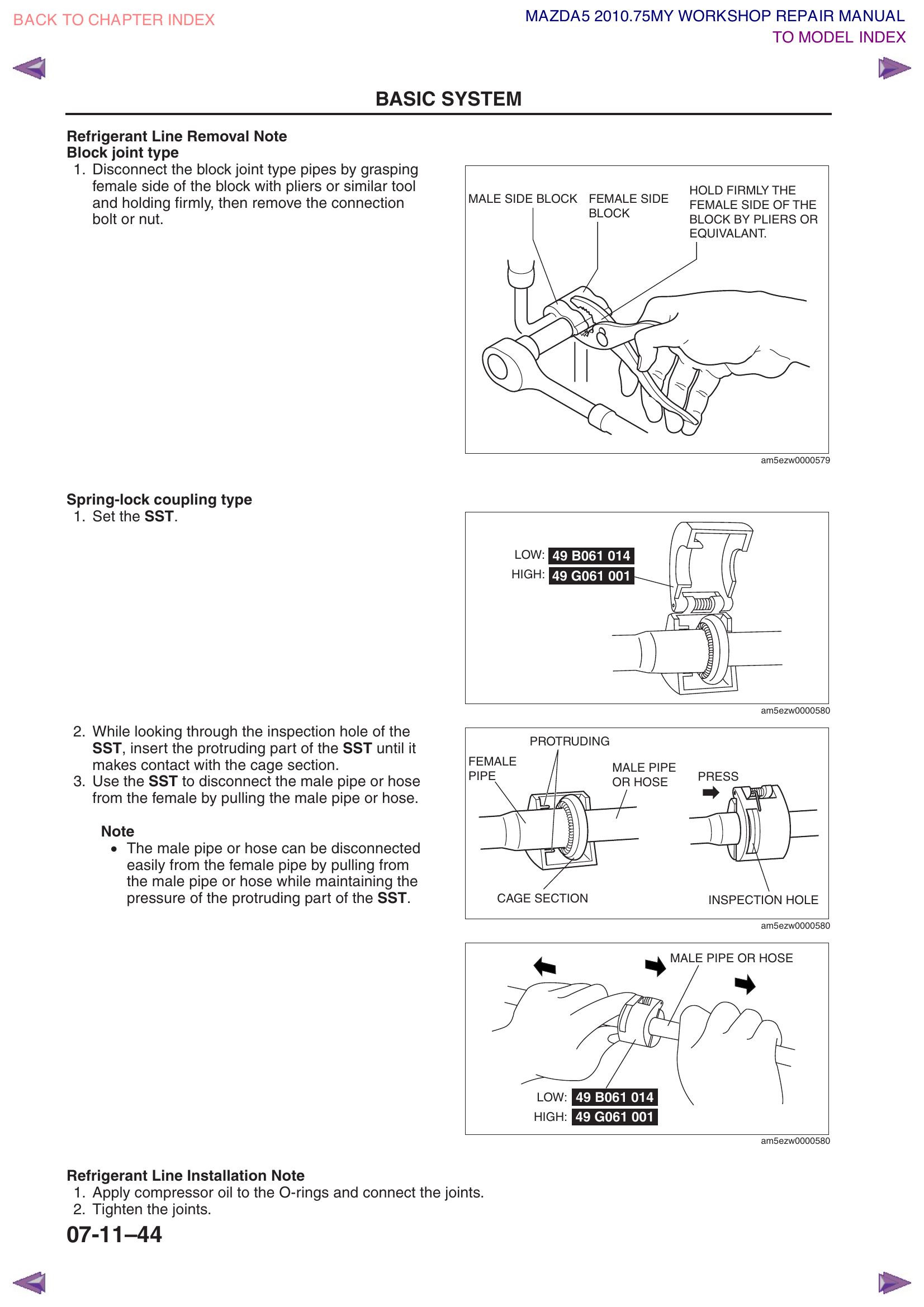
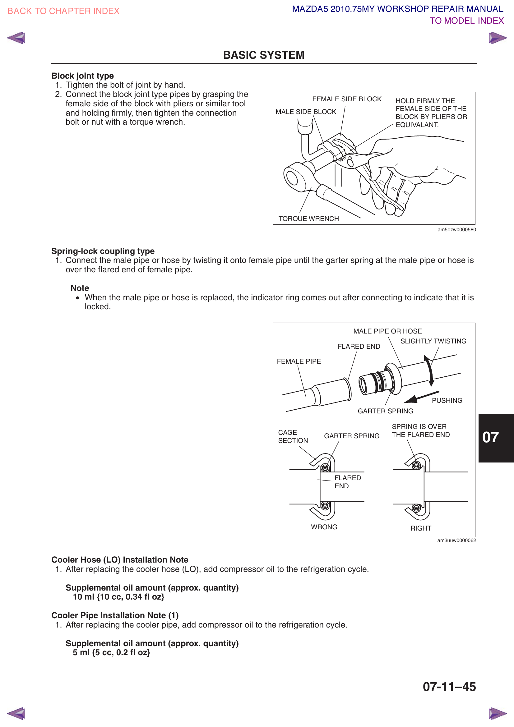
For block joint type connections (most common on the Mazda5):
Hold the female side of the block fitting firmly with pliers or a wrench to prevent it from spinning.
Remove bolt A (torque spec: 6.9–9.8 Nm / 62–86 in-lbf).
Carefully separate the line from the compressor.
For spring lock coupling type connections (if equipped):
Insert the spring lock disconnect tool around the line.
Push the tool inward to compress the garter spring inside the coupling.
While holding the tool in place, pull the male fitting out of the female fitting.
Cap or plug all open fittings. While the vacuum evacuation in Section 11 will pull out residual moisture, capping the fittings keeps dirt, debris, and bugs out of the lines while you work. Use rubber caps, clean rags secured with zip ties, or plastic wrap + rubber bands. This is especially important if the job spans more than one day.
Block joint type (top) and spring lock coupling type (bottom) — how to disconnect eachRefrigerant line bolt, clip, cooler hose HI & LO at compressor
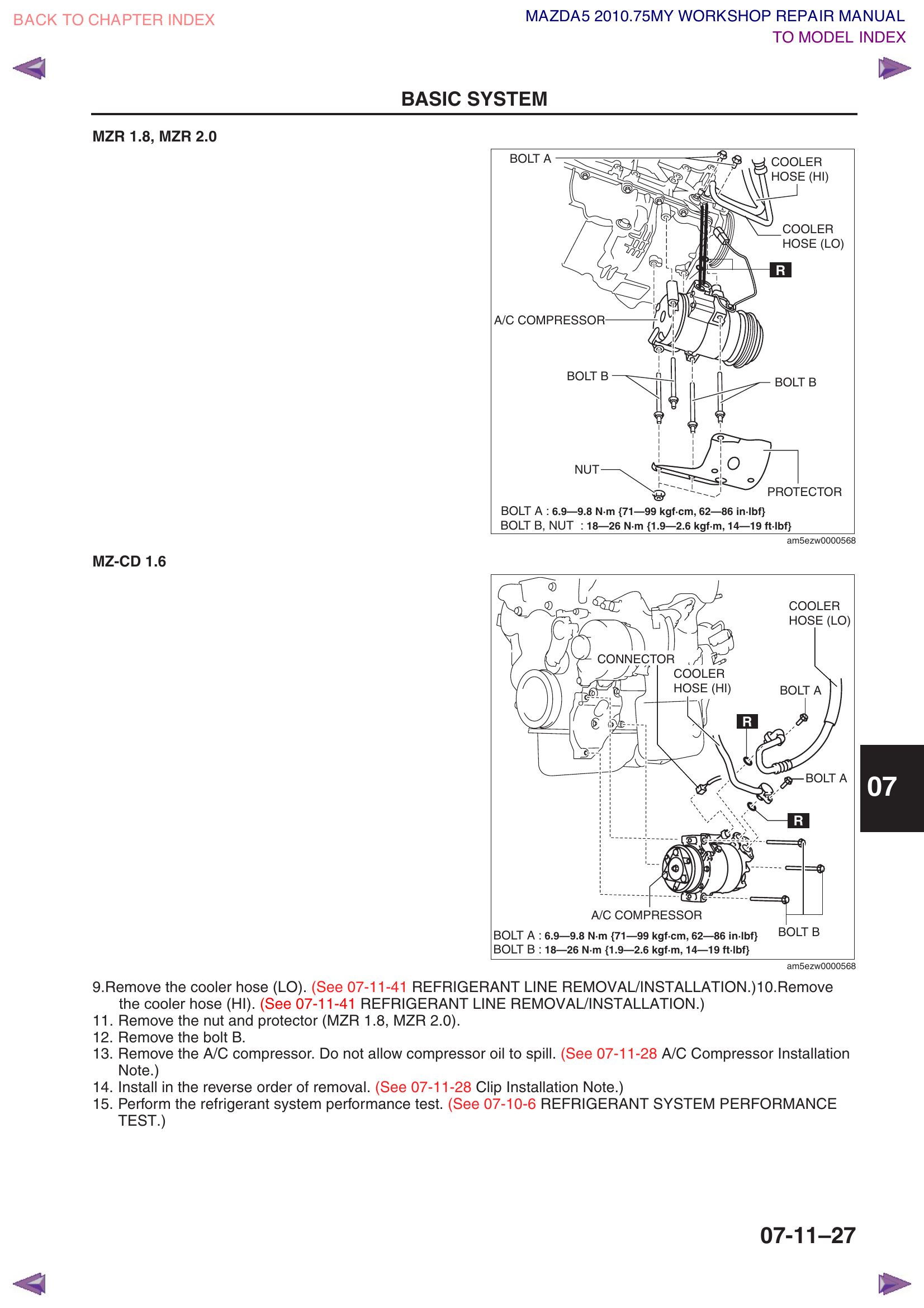
Step 6e — Remove Compressor Mounting Bolts
Remove bolt B (and any additional mounting bolts) — torque spec: 18–26 Nm (14–19 ft-lbf). There are typically 3–4 bolts holding the compressor to the engine block/bracket.
Support the compressor with one hand as you remove the last bolt — it's heavy (about 10–15 lbs).
Carefully lower the compressor out through the bottom of the engine bay (through the space where the under cover was).
Pro Tip: Place a drain pan under the compressor as you remove it. Some residual oil will drip out. Keep the old compressor — you'll need to drain and measure its oil in Step 9a.
Compressor Bolt A (refrigerant line, 6.9–9.8 Nm), Bolt B & Nut (mounting, 18–26 Nm), Cooler Hose HI & LO
Section 7 — Condenser Removal
Workshop Manual Reference: 07-11-28
The condenser sits directly in front of the engine radiator. To remove it, you must remove several components first, then lift the radiator and condenser out together as a unit, then separate them on a workbench.
Step 7a — Remove Plug Hole Plates
Reference: 01-10A-4
These are the plastic/rubber covers on top of the engine that cover the spark plug holes (also called "coil covers" or "engine covers").
Simply lift each plate upward — they sit in rubber grommets/clips.
No tools needed — just pull firmly upward.
Set aside.
Step 7b — Remove Air Cleaner & Fresh Air Duct
Reference: 01-13A-5
The air cleaner assembly (airbox) and its intake ducts need to come out for clearance to access the radiator and condenser.
Disconnect the MAF (Mass Air Flow) sensor electrical connector — press the tab and pull.
Remove the screws and clips holding the air cleaner cover.
Remove the air filter element (good time to inspect/replace it).
Remove the bolts holding the air cleaner box to the vehicle.
Disconnect and remove the fresh air ducts (the intake tubes that connect the airbox to the throttle body). There are typically two pieces (No.1 and No.2).
Set everything aside in order.
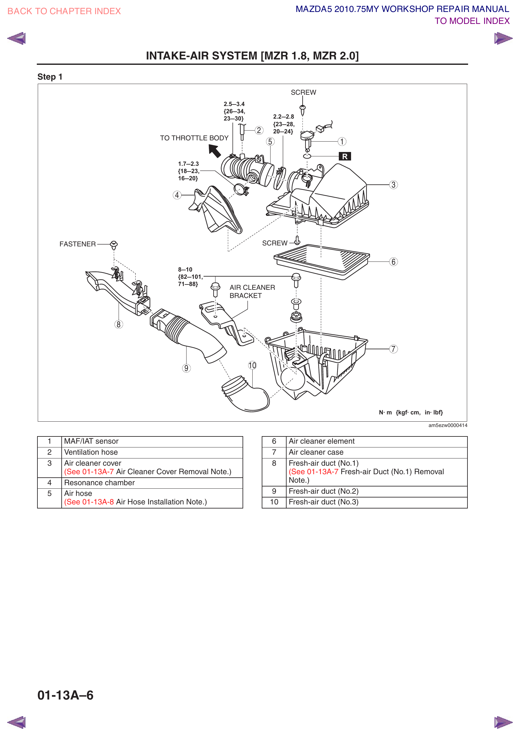
Air cleaner assembly — (1) MAF sensor, (2) Ventilation hose, (3) Air cleaner cover, (4) Resonance chamber, (5) Air hose, (6) Air cleaner element, (7) Air cleaner case, (8) Fresh-air duct No.1, (9) Fresh-air duct No.2, (10) Fresh-air duct No.3. Screw and fastener torque specs shown.
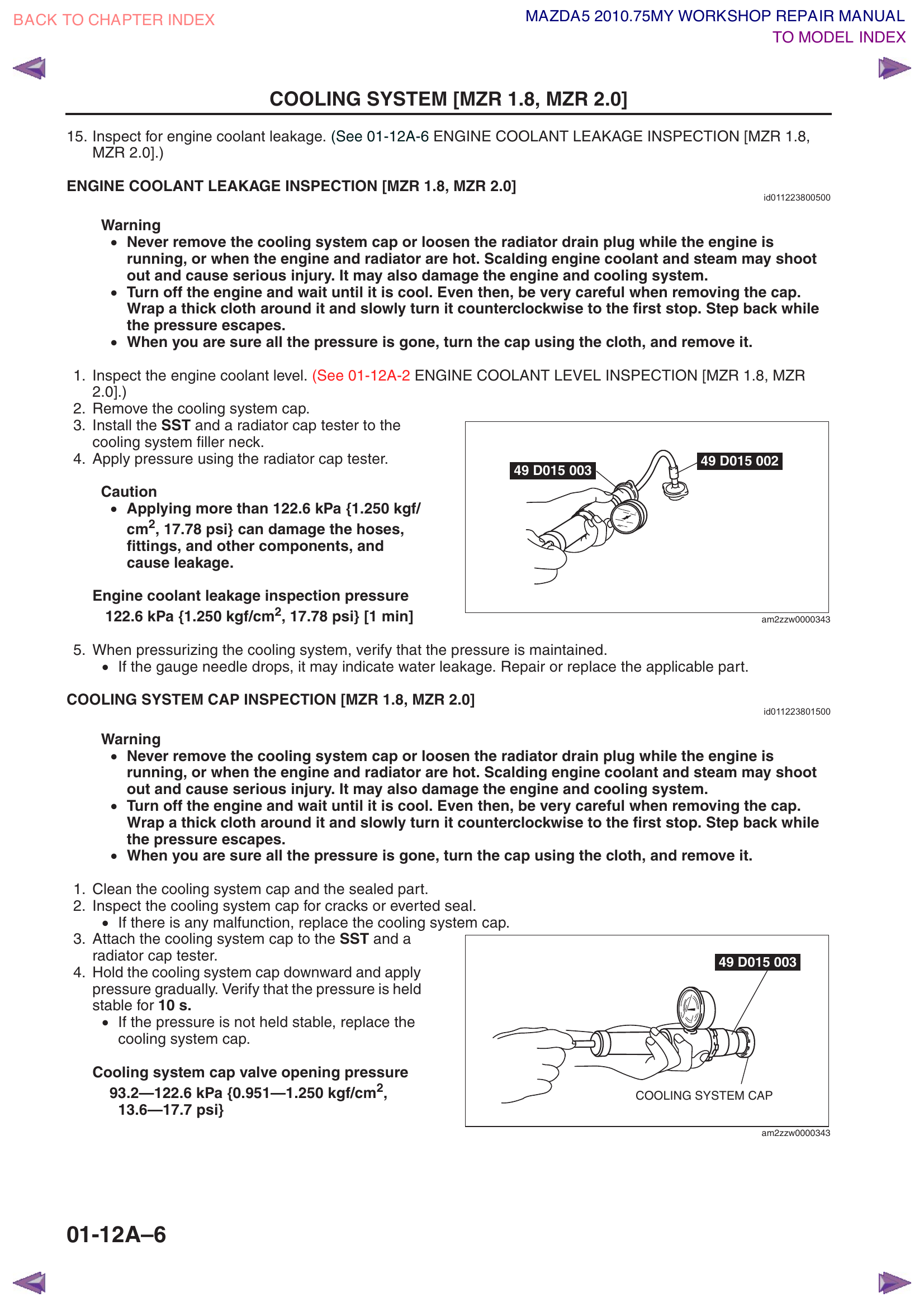
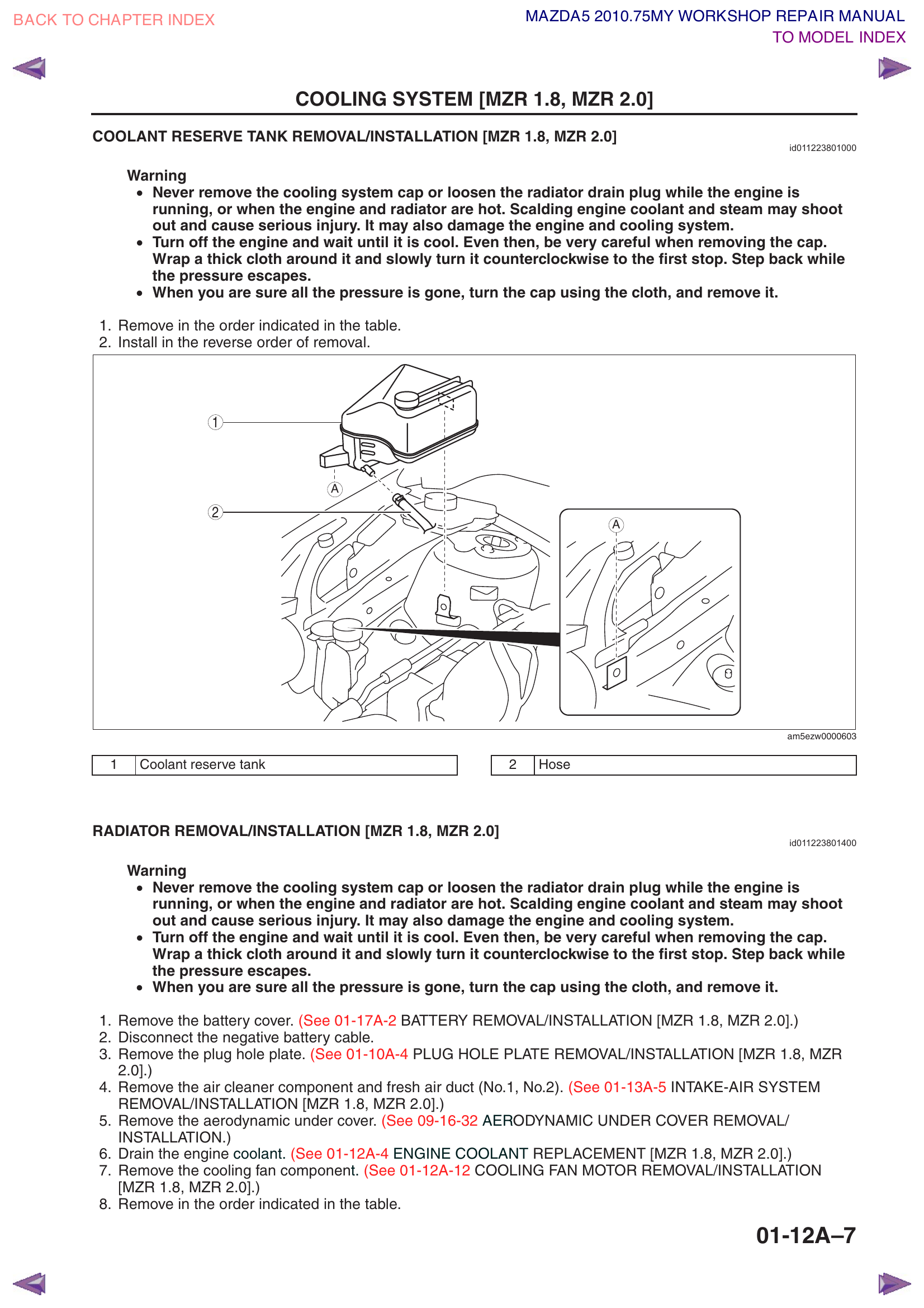
Step 7c — Drain Engine Coolant
Reference: 01-12A-4
WARNING: The engine MUST be completely cool! Hot coolant is under pressure and will spray out, causing severe burns. If the engine has been running, wait at least 2 hours.
Remove the cooling system cap (on the radiator, typically on the passenger side). Turn it slowly and let any residual pressure release before fully removing. "What's the cooling system cap?" — it's the round cap on top of the radiator filler neck, usually near the upper radiator hose.
Place a large drain pan (at least 1 gallon / 4 liter capacity) under the bottom of the radiator.
Locate and open the radiator drain plug (petcock). It's at the bottom of the radiator, usually on the driver's side. It looks like a small plastic wingnut or valve.
Turn it counterclockwise to open. Some have a small nipple you can attach a hose to for a cleaner drain.
Let the coolant drain completely — approximately 3.8 liters will come out. This takes 5–10 minutes.
Close the drain plug when finished. Don't leave it open — you'll forget later.
Coolant is toxic to animals. It tastes sweet and is attractive to pets. Keep drain pans covered and clean up any spills immediately. Dispose of old coolant properly (most auto parts stores accept it for recycling).
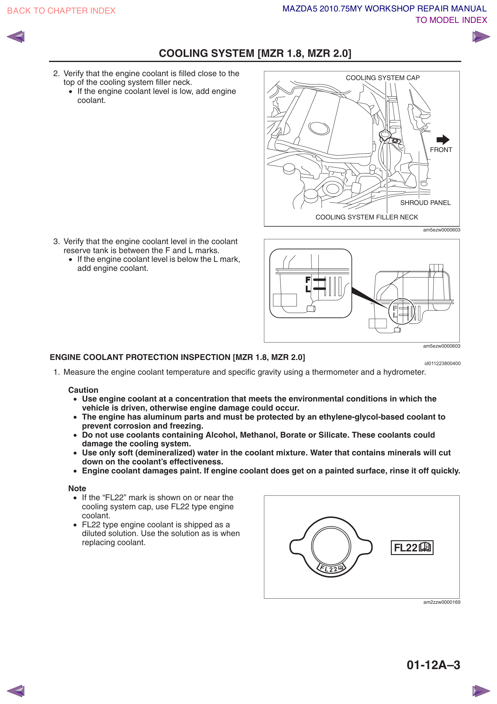
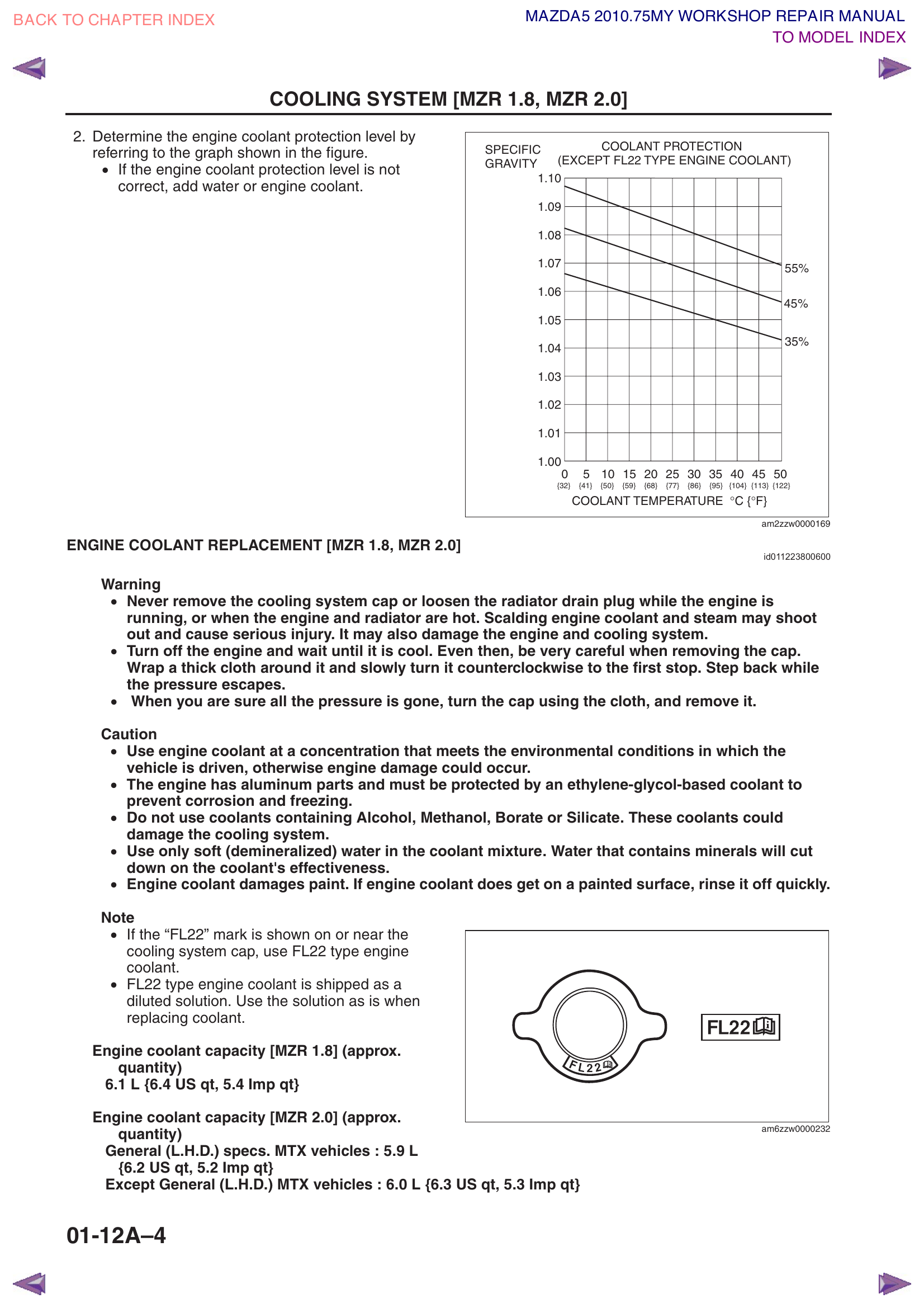
Coolant drain plug locationCoolant specs, FL22 cap marking, and specific gravity chart. Note: capacity numbers shown are for MZR 1.8/2.0 — the 2.5L holds ~7.9L total (~3.8L drains from the radiator).
Step 7d — Remove Cooling Fan Assembly
Reference: 01-12A-12
The cooling fan assembly sits between the radiator and the engine. It must come out before you can remove the radiator.
Disconnect the cooling fan motor connectors. There are typically 2 fans (No.1 and No.2), each with its own electrical connector. Press the tab and pull.
Disconnect the wiring harness from its routing clips.
Remove the mounting bolts (various sizes, torque specs range from 2.8–5.0 Nm to 5.9–8.3 Nm depending on the bolt).
Remove the cooling fan assembly — it comes out from below the engine compartment (drop it down).
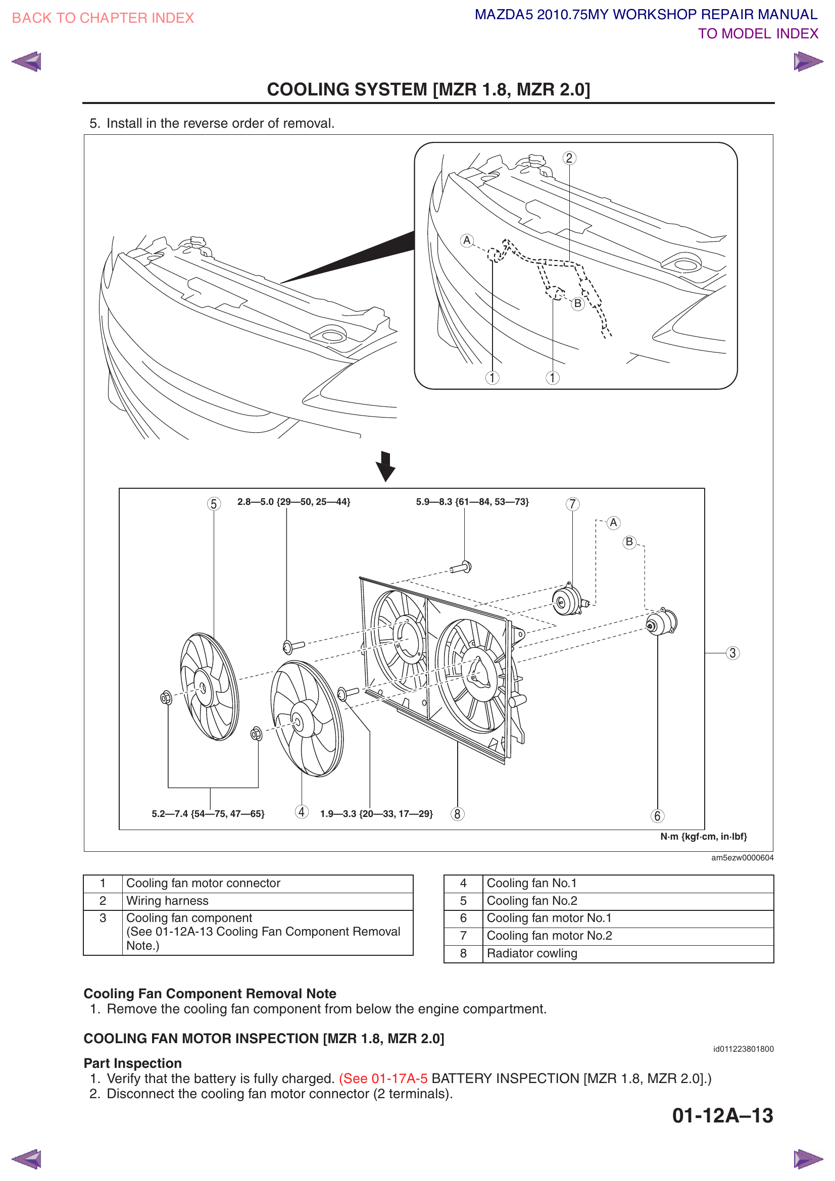
Cooling fan assembly — Components 1–8 labeled: (1) Water pump pulley, (2) Water hose, (3) Cooling fan component, (4) Cooling fan No.1, (5) Cooling fan No.2, (6) Cooling fan motor No.1, (7) Cooling fan motor No.2, (8) Radiator cowling. Bolt torque specs shown at each mounting point.
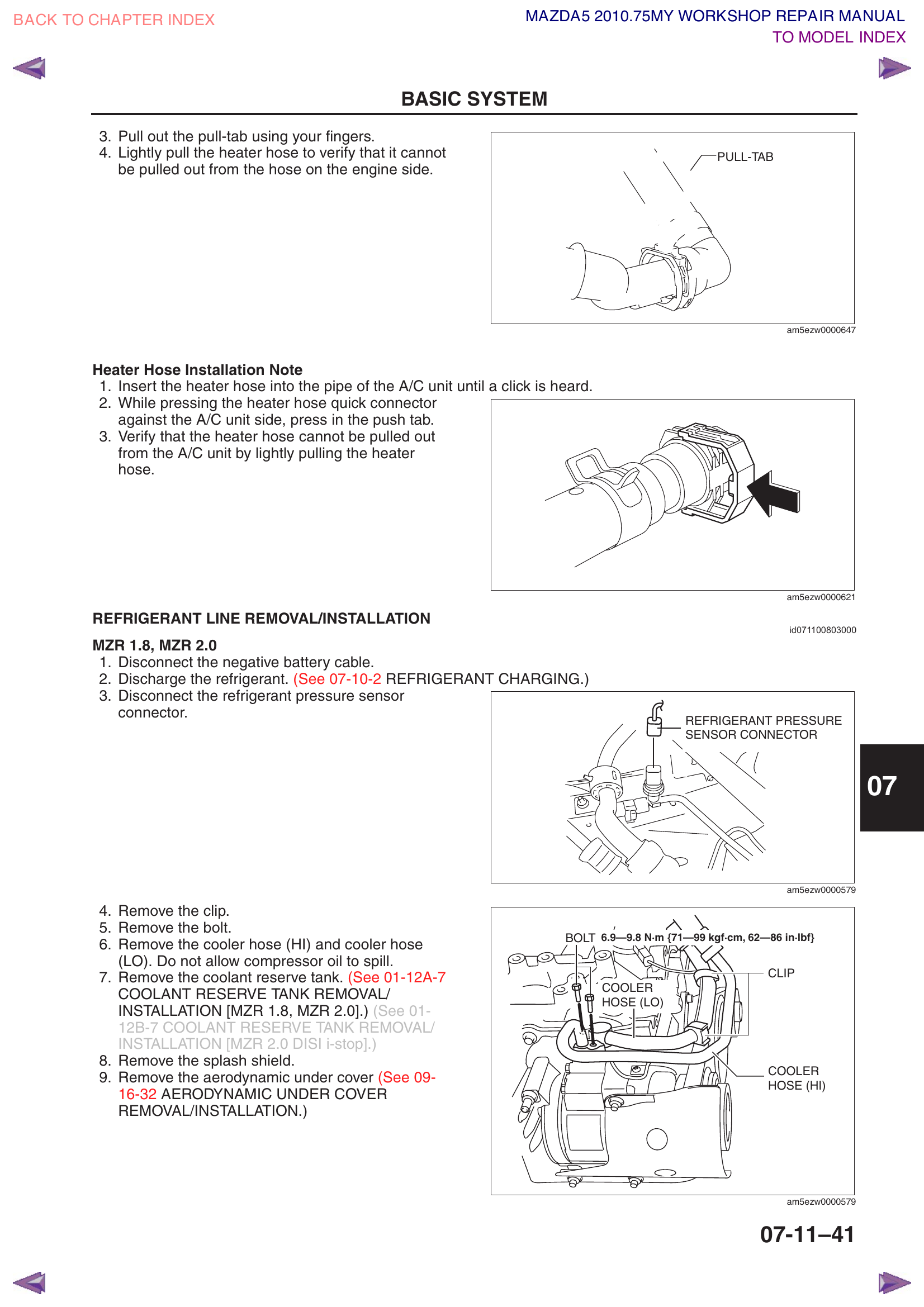
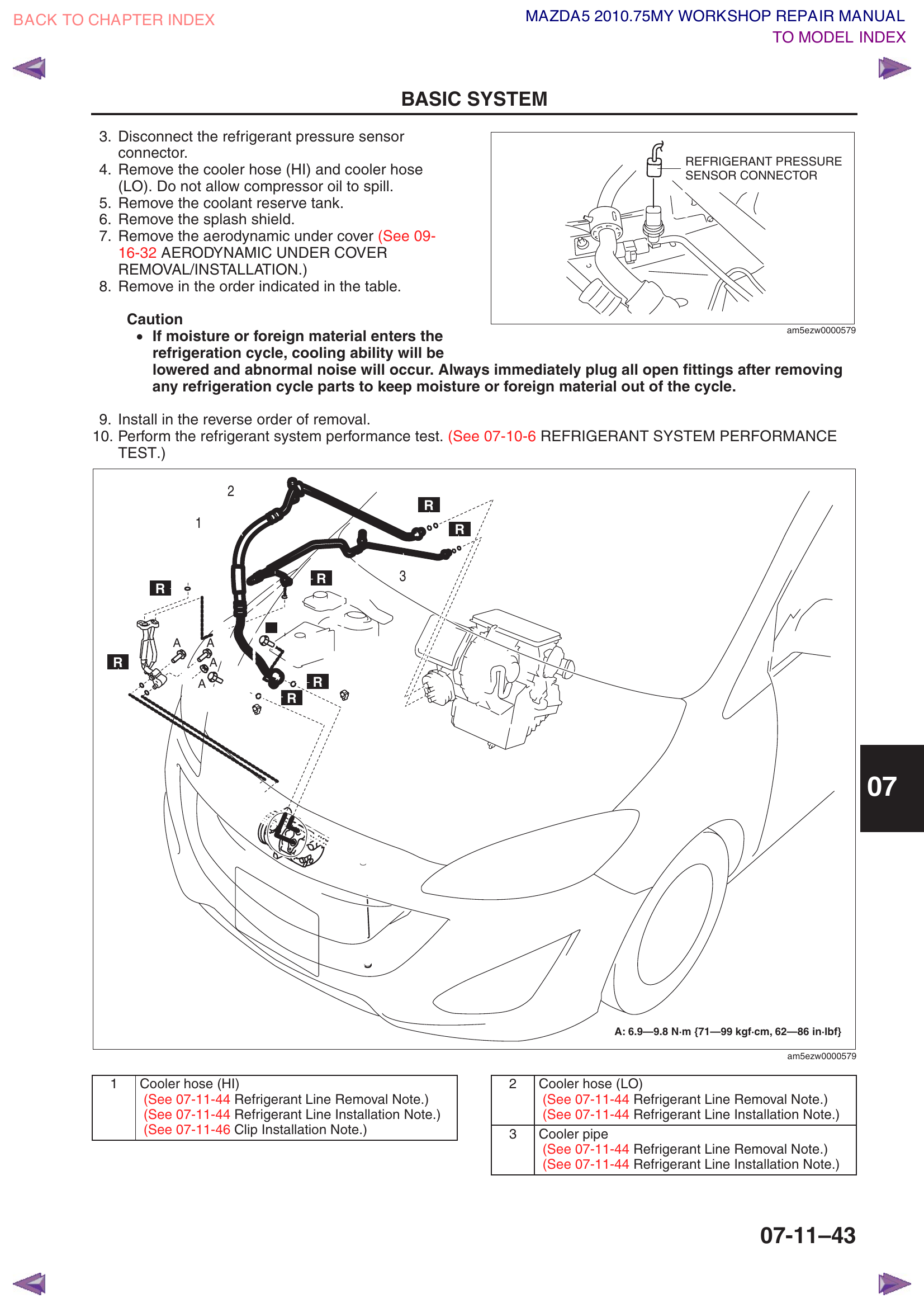
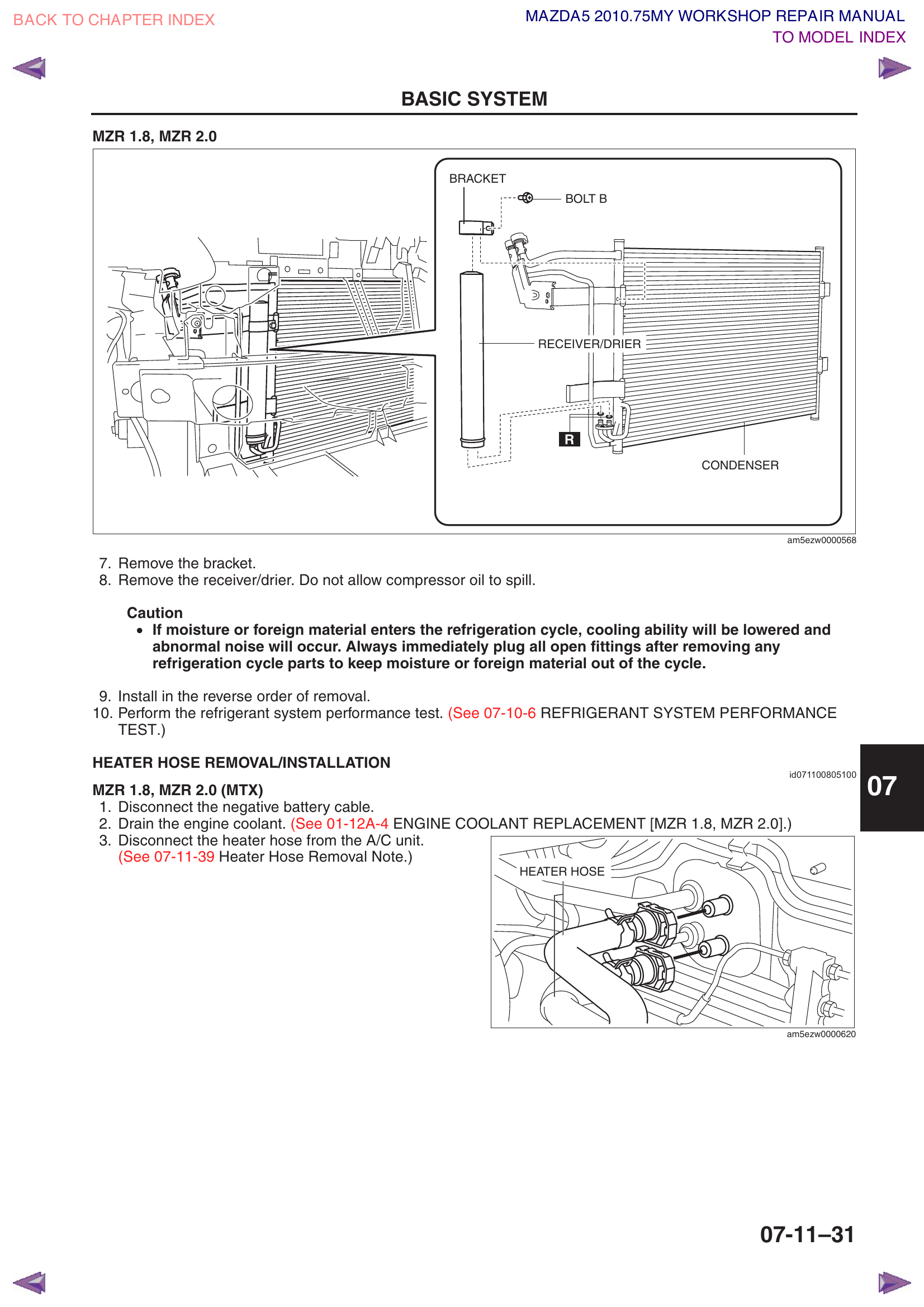
Step 7e — Disconnect Condenser Refrigerant Lines
Disconnect the cooler hose (HI) from the condenser — block joint type connection. Same procedure as Step 6d: hold the female side, remove bolt A.
Disconnect the cooler pipe from the condenser.
Cap or plug the open fittings to keep debris out while you work.
Caution: Some compressor oil will be present in the lines and condenser. Catch any drips with a rag — you don't want oil on the belts or engine.
Full refrigerant line layout — Cooler Hose HI (1), Cooler Hose LO (2), Cooler Pipe (3) — Bolt A: 6.9–9.8 NmEngine bay view — physical location of Cooler Hose HI (1), Cooler Hose LO (2), Cooler Pipe (3), and refrigerant pressure sensor connector. Bolt A: 6.9–9.8 Nm.
The condenser is hooked onto the front of the radiator via tabs. They come out as a single unit.
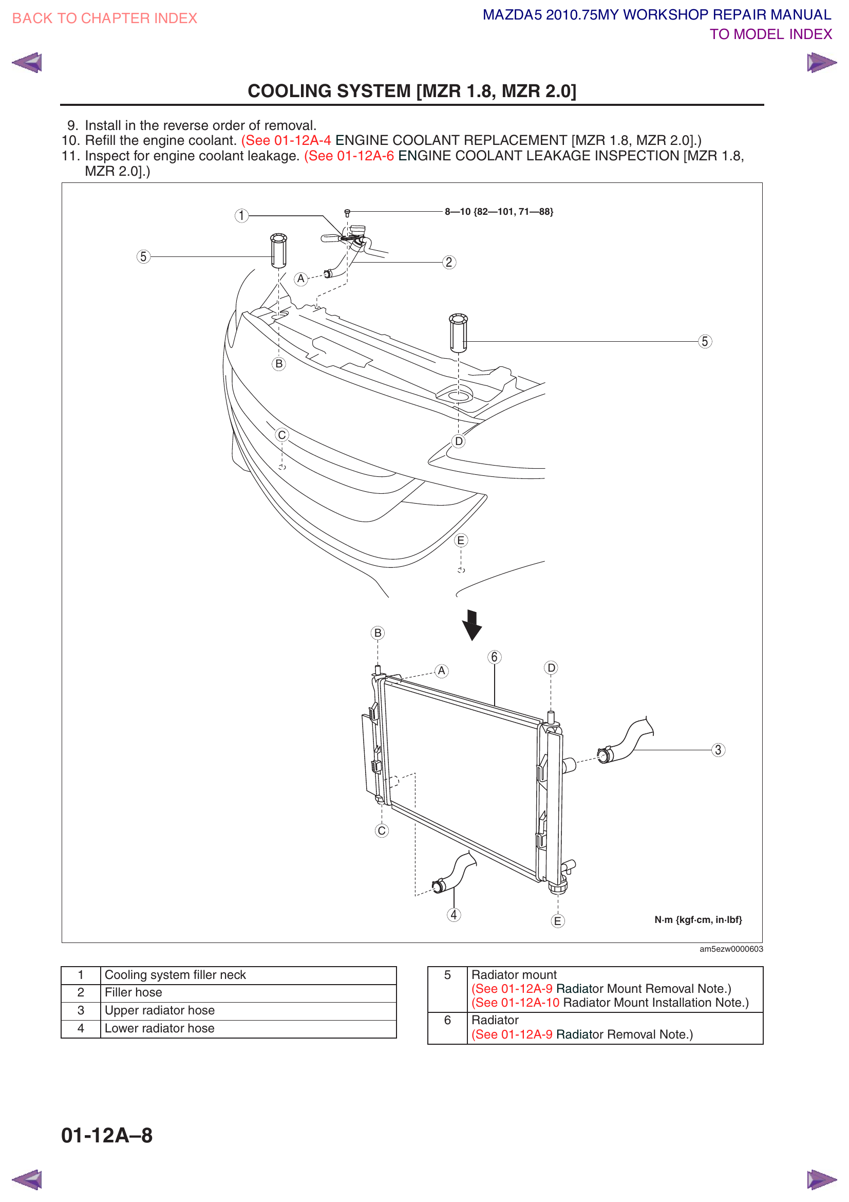
Remove the cooling system filler neck — unbolt and set aside.
Remove the filler hose.
Disconnect the upper radiator hose (squeeze the clamp with pliers, slide it back, then pull the hose off).
Disconnect the lower radiator hose (same method).
Disconnect the automatic transmission cooler lines from the radiator (two metal lines on the lower portion of the radiator). Have a rag ready — some ATF will drip out. These are typically held on with spring clamps or flare nuts.
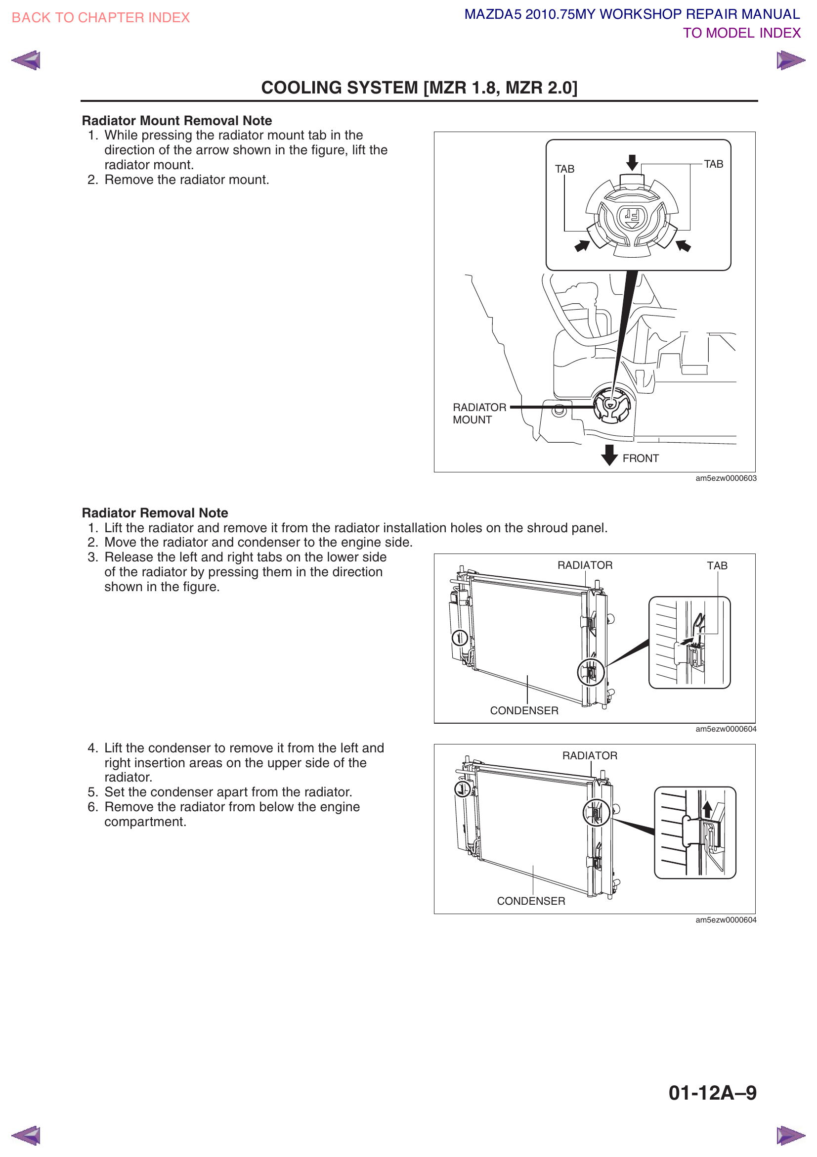
Remove the radiator mounts:
These are rubber-mounted brackets at the top of the radiator.
Press the tabs inward, then lift the mount upward to release.
Carefully lift the radiator + condenser assembly straight up and out of the engine bay. This is a two-person job — have a helper support one side.
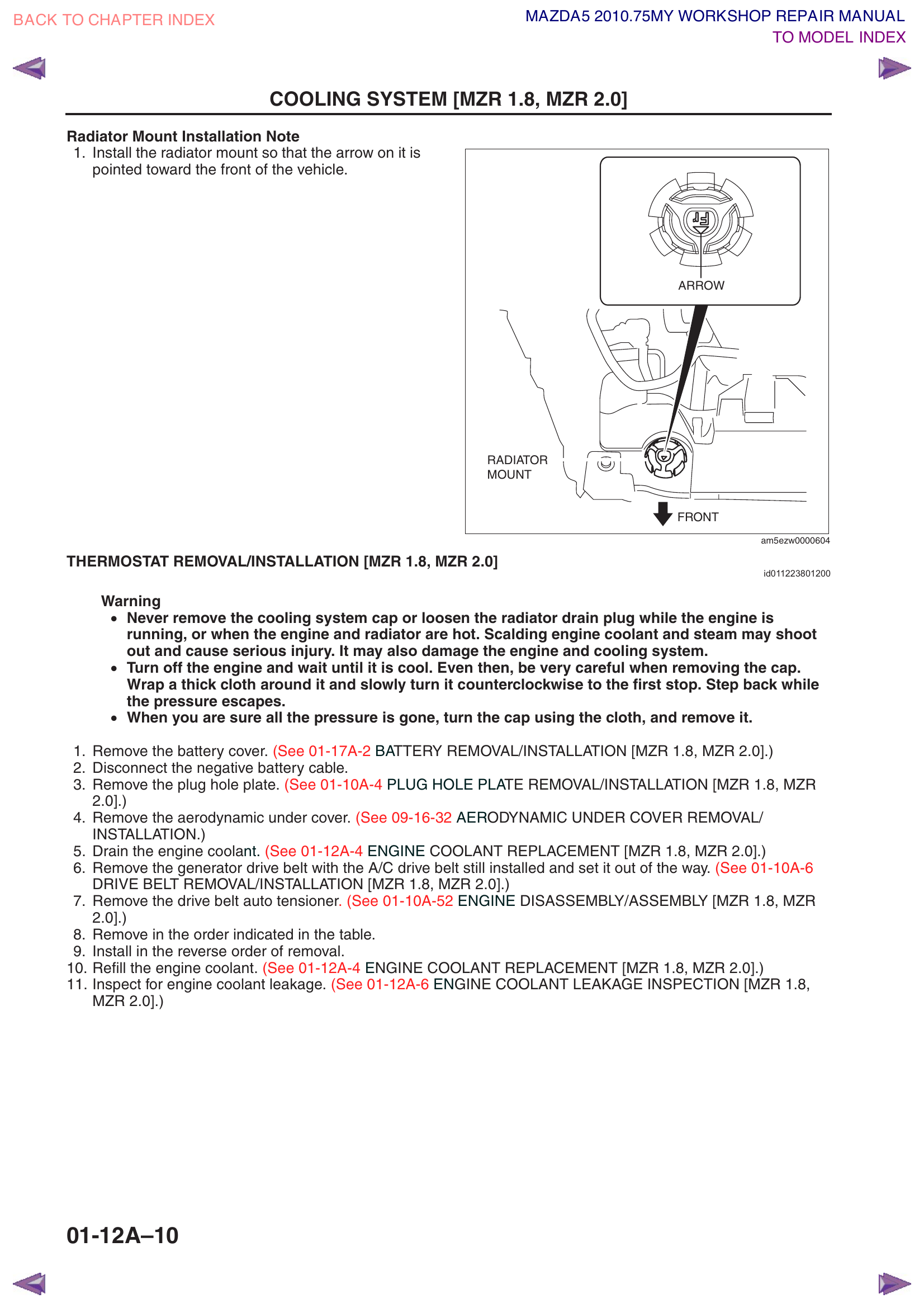
Important: Note the arrow on the radiator mount — it must point toward the front of the vehicle when reinstalling.
Radiator and filler neckRadiator hoses and mountsRadiator mount tab detail
Step 7g — Separate Condenser from Radiator
Lay the radiator/condenser assembly on a clean, padded surface (cardboard or towels). The condenser is aluminum and dents easily.
Look at the lower edge of where the condenser meets the radiator. There are left and right tabs — press them to release.
The condenser hooks onto the upper edge of the radiator at left and right insertion points. Lift the condenser upward to unhook it.
Set the old condenser aside. Keep the radiator — you'll hook the new condenser onto it later.
Condenser/Radiator separation — receiver/drier locationCondenser hook and tab details
Section 8 — Receiver/Drier Removal — Skipped
Our replacement condenser has the receiver/drier integrated (attached directly to the condenser), so there's no need to remove the old standalone receiver/drier or take off the front bumper to access it. The old receiver/drier stays in place behind the bumper — its lines were already disconnected in Step 7e.
Note: If your replacement condenser does not have the receiver/drier built in, you'll need to remove the front bumper and swap the receiver/drier separately. Refer to Workshop Manual 07-11-30 (receiver/drier) and 09-10-14 (front bumper removal).
Section 9 — Installation (Reassembly)
Now we install the new components. Installation is essentially the reverse of removal, but with some critical steps for the AC system specifically.
Critical Rules for AC Installation:
Replace ALL O-rings at every connection with new ones from your kit.
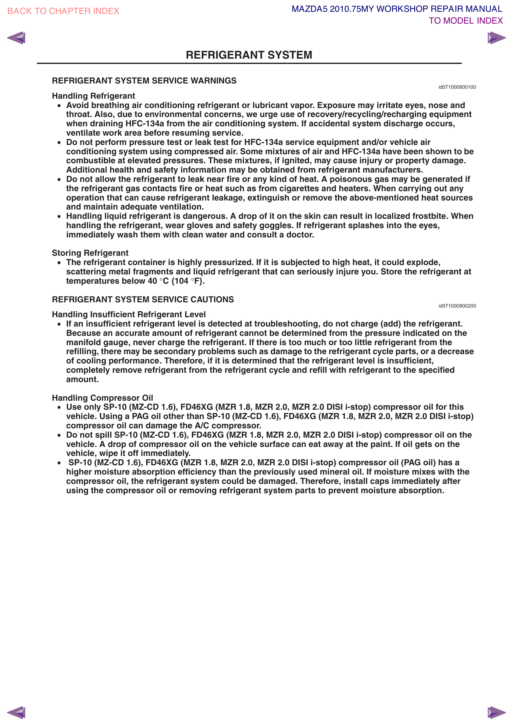
Apply a thin film of PAG 46 compressor oil to each new O-ring before installing — this helps them seal and prevents tearing.
Keep fittings clean — do NOT let debris, dirt, or metal shavings enter any open fitting. Even a small piece of grit can cause a leak or damage the new compressor.
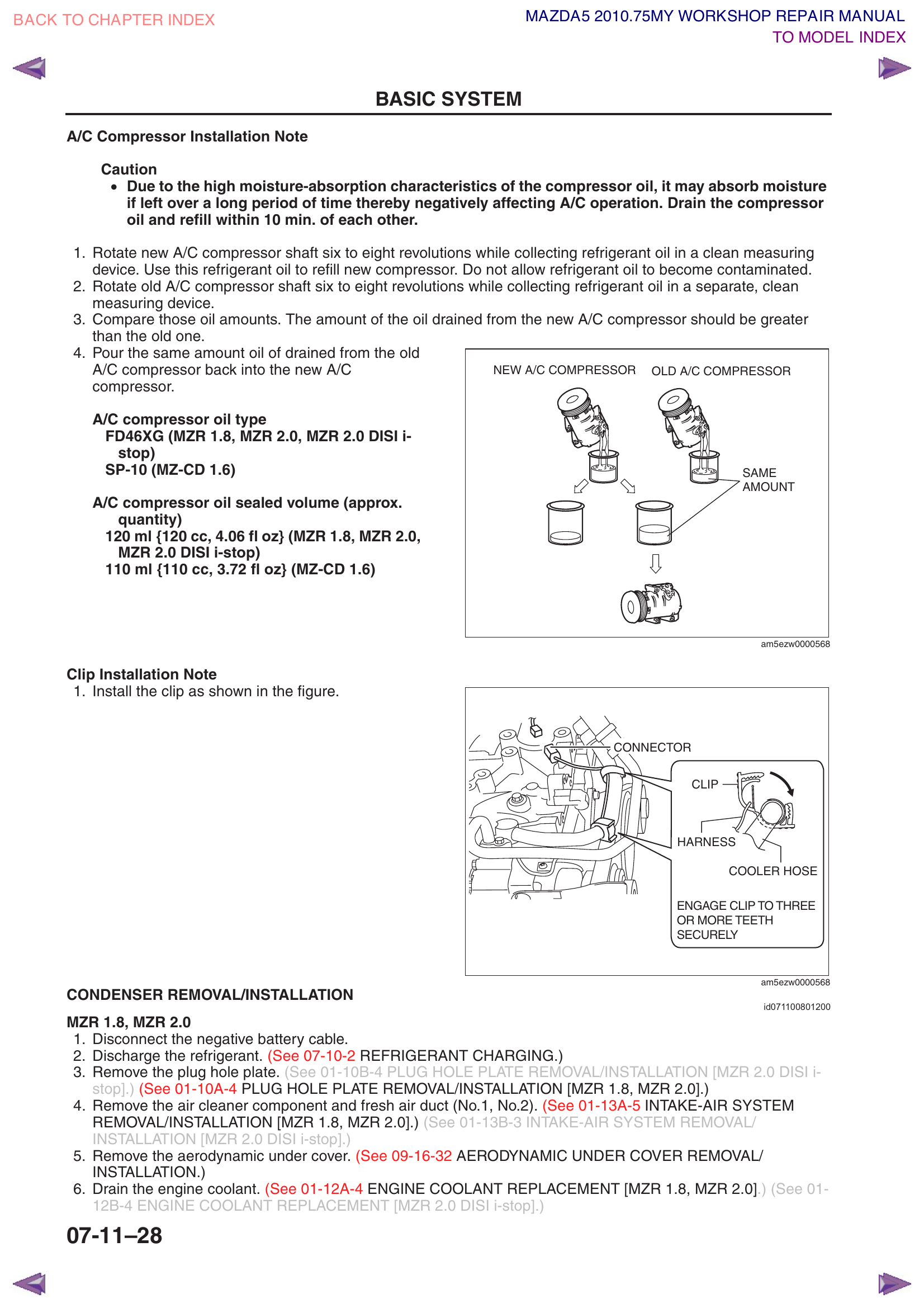
Step 9a — Prepare New Compressor (CRITICAL Oil Balancing Procedure)
New compressors come pre-filled with oil, but usually too much for your system. You need to balance the oil amount to match what was in your old system.
Take the NEW compressor. Remove the cap from the suction port. Rotate the compressor shaft by hand (using a wrench on the clutch center bolt) 6–8 full revolutions. This pumps oil out of the internal chambers.
Pour the oil that comes out into a clean measuring cup. Note the amount. This is the "new compressor oil amount."
Take the OLD compressor. Rotate its shaft 6–8 revolutions. Collect that oil in a separate clean container. Note the amount. This is the "old compressor oil amount."
Compare:
The new compressor should have more oil than what came out of the old one.
If the old compressor is seized and you can't rotate the shaft: skip measuring the old one. Instead, drain and measure only the new compressor, then pour back approximately 80–90 ml (roughly 2/3 of the total 120 ml system capacity, since some oil remains distributed in the lines and evaporator).
If the old compressor turns but very little oil comes out, that's normal — oil migrates throughout the system during operation.
Pour the same amount of oil that came out of the OLD compressor back into the NEW compressor through the suction port. (Or use the 80–90 ml estimate if the old compressor was seized.)
Oil type: FD46XG / PAG ISO 46
Total sealed system volume: 120 ml (4.06 fl oz)
Do this quickly! PAG oil absorbs moisture from the air rapidly. Complete the oil transfer and re-cap the compressor within 10 minutes. Work in a dry environment if possible.
Add 35 ml of supplemental PAG 46 oil into the new condenser (pour it into the inlet fitting). This replaces oil that was trapped in the old condenser.
With the radiator laying on a flat surface, position the new condenser in front of it.
Hook the condenser onto the radiator at the upper left and right insertion points (the condenser hooks over the top edge of the radiator).
Press the lower tabs into place until they click/snap.
Verify the condenser is firmly attached and aligned with the radiator.
Step 9c — Install Radiator/Condenser Assembly
With a helper, lower the radiator (with new condenser) back into the engine bay.
Seat the radiator into the shroud panel installation holes at the bottom.
Install the radiator mounts:
Remember: Arrow must point toward the front of the vehicle!
Press tabs inward to lock.
Reconnect the lower radiator hose — push on fully, slide clamp back into position.
Reconnect the upper radiator hose — same method.
Reconnect the ATF cooler lines to the lower portion of the radiator.
Reinstall the filler hose and filler neck (bolts: 8–10 Nm).
Radiator mount installation — the arrow on the mount MUST point toward the front of the vehicle.Radiator mount tab detail — press tab in direction of arrow to lift mount. Also shows condenser-to-radiator insertion areas and tab locations.
Step 9d — Reinstall Cooling Fan Assembly
Slide the fan assembly up from below into position between the radiator and engine.
Install all mounting bolts and torque to spec (2.8–8.3 Nm range, varies by bolt).
Reconnect both fan motor connectors (you'll hear a click when they lock).
Route the wiring harness back through the original clips.
Cooling fan assembly — bolt torque specs shown at each mounting point. See Step 7d for component reference.
Step 9f — Install New Compressor
Lift the new compressor into position from below.
Install mounting bolts B and torque to 18–26 Nm (14–19 ft-lbf). Start all bolts finger-tight first, then torque in a cross pattern.
Install new O-rings on both refrigerant line connections. Apply PAG 46 oil.
Connect the refrigerant lines and tighten bolt A: 6.9–9.8 Nm.
Reconnect the electrical connector (push until it clicks).
Reinstall the wiring harness clip — engage to 3 or more teeth to lock.
Reinstall the water hose bracket.
Compressor mounting — Bolt A (refrigerant lines, 6.9–9.8 Nm), Bolt B/Nut (mounting, 18–26 Nm), Cooler Hose HI and Cooler Hose LO connections. See Step 6e for reference.Block joint installation — hold female side with pliers, tighten with torque wrench. Spring lock coupling — twist male pipe onto female until indicator ring pops out. Supplemental oil: Cooler Hose LO = 10 ml, Cooler Pipe = 5 ml.Water hose bracket, electrical connector, and wiring clip locations at the compressor.
Step 9g — Drive Belt Installation (2.5L)
Route the belt according to the belt routing diagram below (or from your photo / engine bay sticker). Make sure it wraps around every pulley in the correct pattern — getting this wrong can cause immediate damage.
Leave the belt off one pulley (typically the tensioner pulley or an idler).
Place the 14mm socket on a breaker bar on the auto-tensioner bolt and rotate clockwise (toward front of car) to release tension.
Slip the belt onto the last pulley.
Slowly release the tensioner — it will automatically apply the correct tension.
Verify: Check that the belt is properly seated in ALL pulley grooves. A misaligned belt will squeal, throw off, or cause damage.
Rotate the crankshaft clockwise by hand for 2 full rotations (use a socket on the crankshaft pulley bolt) to verify the belt tracks correctly and doesn't interfere with anything.
Belt routing reference — see Step 6a for full pulley legend.
NEVER rotate the crankshaft counterclockwise — this can loosen the crankshaft bolt.
Step 9h — Reinstall Remaining Components
Air cleaner and fresh air duct — reverse of Step 7b. Reconnect the MAF sensor.
Plug hole plates — push down into the rubber grommets.
Aerodynamic under cover — reinstall fasteners C, bolts B, screws A (Section 4).
Reconnect negative battery cable — tighten the 10mm nut securely.
Section 10 — Refill Engine Coolant
Workshop Manual Reference: 01-12A-4
Verify the radiator drain plug is closed/tight.
Prepare coolant mixture:
Climate
Coolant %
Water %
Freeze Protection
Moderate (most US areas)
55%
45%
-37°C / -35°F
Severe cold
60%
40%
-51°C / -60°F
Hot climate / no freeze risk
50%
50%
-37°C / -35°F
Use Mazda FL22 or equivalent long-life coolant. Use distilled water (not tap water) for the mix. Or buy pre-mixed coolant.
Pour coolant slowly into the radiator filler neck until the level reaches near the top. Go slowly — air bubbles need time to escape.
Fill the coolant reserve tank (the translucent plastic tank with MIN/MAX marks) to the "F" (Full) mark.
Install the cooling system cap.
Start the engine and let it warm up to operating temperature (the temperature gauge will reach its normal position).
Run the engine at 2,500 RPM for 5 minutes. This circulates coolant and helps push air bubbles out.
Then: Rev to 3,000 RPM for 5 seconds, then return to idle. Repeat this 3–5 times. This "burping" procedure helps purge trapped air from the system.
Turn off the engine and let it cool completely.
Check the coolant level again — top up if needed (both radiator and reserve tank).
Check for leaks at all hose connections and the drain plug.
Pro Tip: Check the coolant level again after driving for a day or two. Air pockets may work themselves out and the level may drop slightly. Top up as needed.
Section 11 — Evacuate & Charge AC System
Workshop Manual Reference: 07-10
This is the final step for the AC system. You'll pull a deep vacuum to remove all air and moisture, then charge with the exact amount of R-134a refrigerant.
If you used the manifold gauges for recovery in Section 3.5, you're already familiar with the setup. If your recovery machine had its own gauges and you're using a separate gauge set for this step, connect them the same way:
Ensure the engine is OFF and both manifold valves are closed (turned fully clockwise).
Connect the blue (low-side) hose to the low-pressure service port (larger fitting, near firewall).
Connect the red (high-side) hose to the high-pressure service port (smaller fitting, near condenser).
Connect the yellow (center) hose to the vacuum pump inlet.
Both gauges should currently read at or near 0 psi (since the system is empty after your work).
Step 2: Evacuate the System (Pull a Vacuum)
Why: Even though you recovered the old refrigerant, the system has been open to the atmosphere during the repair. Air and moisture are now inside. A vacuum pump removes all air and boils off any moisture at low pressure — water inside the AC system causes corrosion, ice blockages, and acid formation.
Make sure the engine is OFF.
Verify the center (yellow) hose is securely connected to the vacuum pump.
Open both manifold valves (turn the blue and red knobs counterclockwise). This allows the pump to pull vacuum from both the high and low sides of the system simultaneously.
Turn on the vacuum pump.
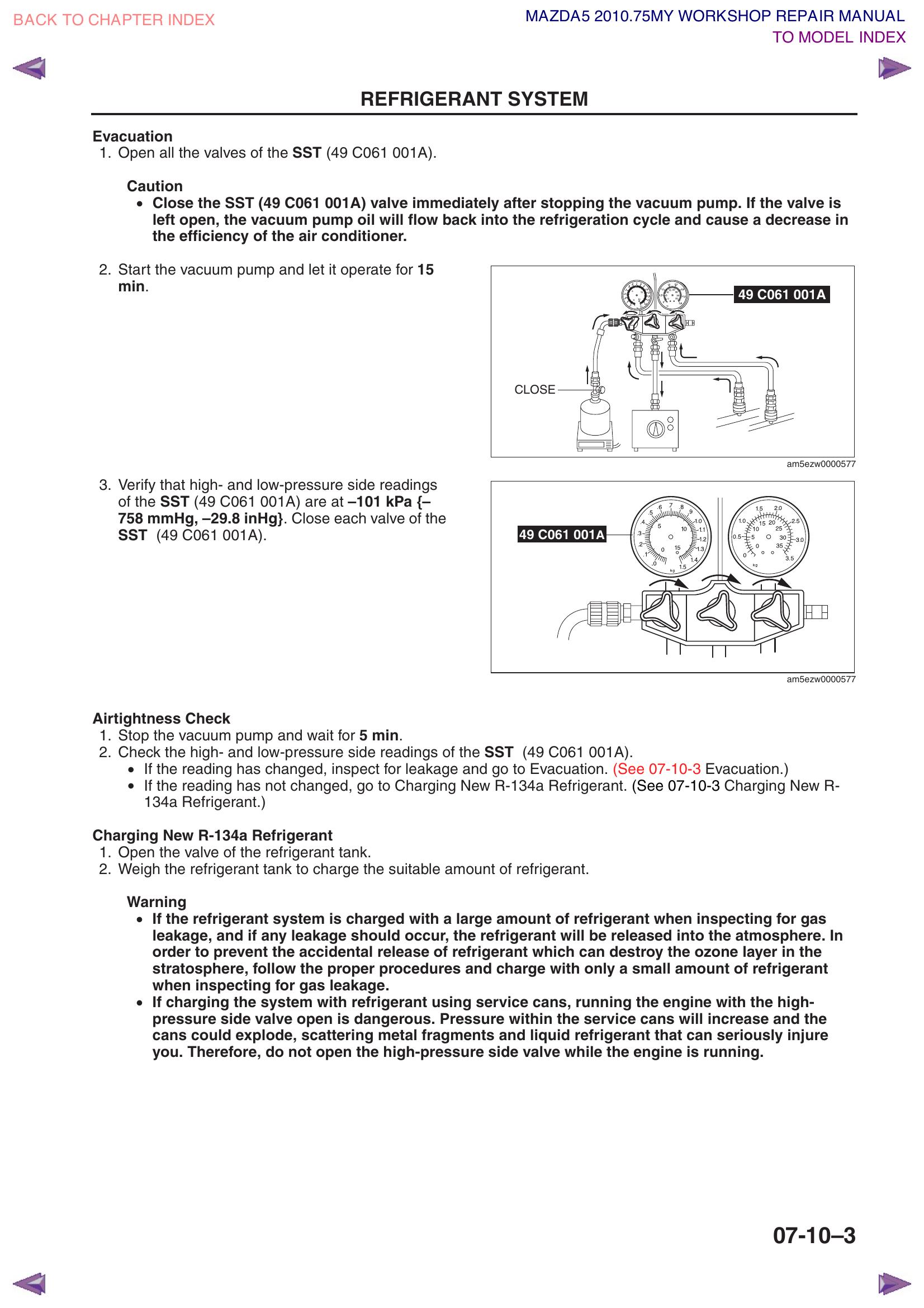
You should immediately see the low-side (blue) gauge needle drop below 0 and begin moving into the vacuum range (the numbers below 0 on the gauge, measured in inches of mercury / inHg).
Let it run for at least 30 minutes. If the system was open for more than a few hours or in humid conditions, run for 45–60 minutes.
Verify the low-side gauge reads -29.8 inHg or lower (some gauges show this as "30" on the vacuum scale). This confirms a deep vacuum. The high-side gauge may also show vacuum but isn't calibrated for it — focus on the blue gauge.
Close both manifold valves (turn clockwise until snug).
Turn off the vacuum pump.
Wait at least 15 minutes and watch the low-side gauge carefully.
Leak Check (CRITICAL): During the 15-minute wait, the low-side gauge needle must not move. If the pressure rises (needle moves toward 0):
Small rise (1–2 inHg): Could be a very slow leak at an O-ring or the gauge set's own connections. Re-check all fittings and O-rings, re-torque the block joint bolts, and re-evacuate.
Steady rise back toward 0: Significant leak. Do NOT proceed with charging. Use your electronic leak detector at every connection point. Fix the leak, then re-evacuate.
Common leak culprits: under-torqued block joint bolts, pinched or missing O-rings, damaged Schrader valve in a service port, or a loose hose connection on the gauge set itself (test by closing valves and checking if the gauge still rises).
If the vacuum holds steady for 15 minutes: Your system is sealed and moisture-free. Proceed to charging.
Step 3: Charge with R-134a
What happens during charging: You're going to let pressurized refrigerant from cans flow into the evacuated (vacuum) system. The vacuum pulls the refrigerant in initially. Once the engine is running and the compressor is spinning, the compressor's suction pulls the remaining refrigerant in through the low side.
3a. Connect the Refrigerant
Both manifold valves must be CLOSED.
Disconnect the yellow center hose from the vacuum pump.
Screw a can tap valve onto your R-134a can (if using 12 oz cans). Make sure the tap valve is in the closed position (knob turned all the way out).
Connect the yellow center hose to the can tap valve.
Turn the can tap knob all the way in to puncture the can, then back it out half a turn to open the flow path.
Place the can on your digital scale. Note and record the starting weight (e.g., "can + tap = 428g").
3b. Purge the Center Hose
The center hose is full of air (from disconnecting the vacuum pump). You need to push that air out before opening it to the system:
With both manifold valves still CLOSED, slightly loosen the center hose fitting at the manifold (where the yellow hose connects to the gauge body — NOT at the can end).
You'll hear a brief hiss as refrigerant pressure from the can pushes air out of the hose.
After 2–3 seconds, retighten the fitting. The center hose is now full of refrigerant instead of air.
3c. Initial Charge (Engine OFF)
With the engine still OFF, open the low-side (blue) valve only.
Refrigerant will flow from the can into the evacuated system. You'll see the low-side gauge rise from vacuum toward a positive pressure. The can will get cold as liquid refrigerant evaporates out of it.
Let it flow until the pressure stabilizes and you stop hearing flow (typically 1–3 minutes). The system will equalize around 40–60 psi depending on ambient temperature.
Close the low-side valve.
3d. Running Charge (Engine ON)
Start the engine.
Turn the AC to MAX COLD, fan to MAX speed, set to recirculate mode.
The compressor clutch should engage (you may hear a click and see the center of the compressor pulley begin to spin). If it doesn't engage, that's normal — many compressors need a minimum charge before the low-pressure safety switch allows engagement.
Open the low-side (blue) valve. Refrigerant will now be pulled in by the compressor's suction.
Watch the gauges:
Low side should read 25–45 psi during charging (varies with ambient temp and charge level).
High side should read 150–250 psi (roughly 2–2.5x the ambient temperature in °F, e.g., 80°F day ≈ 160–200 psi).
You can hold the can upside down briefly to let liquid refrigerant flow out faster (liquid charges faster than gas). This is safe on the low side as long as the compressor is running — it will vaporize the liquid before it reaches the compressor.
Monitor the scale. When the first can is empty, close the low-side valve, disconnect the empty can, attach a new one, tap it, purge the hose again, and continue.
Keep charging until the scale shows a total of 480g (16.9 oz) has been added across all cans.
How to track weight across multiple cans: Record the starting weight of each can. After each can, record the ending weight. Sum the differences. Example: Can 1 started at 428g, ended at 100g = 328g used. Can 2 started at 430g, you need 152g more, so stop when it reads 278g.
NEVER open the high-side (red) valve with the engine running! The high side can be at 200+ psi — far higher than the can pressure. Opening the red valve would force high-pressure refrigerant backward into the can, which could cause it to explode. Low side ONLY when the engine is running.
What if the compressor won't engage? Some compressors have a low-pressure cutoff switch that prevents engagement until there's enough refrigerant in the system. If the compressor clutch won't kick in after adding the initial charge (engine off), try this: with the engine running and AC on MAX, have a helper briefly jumper the compressor clutch connector (the single wire on the compressor) to force it on. This will start pulling refrigerant in. Once enough charge enters the system, the pressure switch will take over. Alternatively, keep adding refrigerant slowly with the engine running — it will flow in by temperature/pressure differential, just more slowly without the compressor pulling.
Step 4: Verify Charge and Disconnect
With the full 480g charge in the system and the engine running with AC on MAX:
The low-side gauge should read 25–35 psi (depending on ambient temp).
The high-side gauge should read 150–250 psi.
If the low side is too high (50+ psi), the system may be overcharged or the condenser fans aren't running.
If the low side is too low (<20 psi), the system may be undercharged or there's a restriction.
Close both manifold valves.
Turn off the engine.
Disconnect the gauge hoses from the service ports — pull back the quick-connect collar and pull straight off. A small hiss as residual hose pressure releases is normal (this is just the tiny amount trapped in the hose, not a system leak).
Reinstall the protective caps on both service ports. Finger-tight is fine.
Refrigerant system — service overviewEvacuation procedureCharging procedureSystem performance test
Section 12 — Final Testing & Verification
Start the engine and let it idle at approximately 1,500 RPM (slight throttle or fast idle is fine).
Set AC to MAX COLD, fan on MAX HI, recirculate mode, all windows closed.
Let the system run for 5–10 minutes to stabilize.
Check vent temperature with a thermometer inserted into the center dash vent:
Target: 35–45°F (2–7°C) depending on ambient temperature.
On a hot day (90°F+), 45–50°F is acceptable.
If vent temp is above 55°F, there may be an issue (undercharge, air in system, or a leak).
Listen for unusual compressor noises:
Clicking/rattling: may indicate debris in the system or a clutch issue.
Grinding/squealing: bearing failure or belt issue.
Normal sound: a slight hum/drone when the compressor clutch engages.
Leak check: Use your electronic leak detector to sniff around every refrigerant connection point (compressor fittings, condenser connections, receiver/drier, service ports).
Check coolant level and connections: Look for any drips at radiator hoses, drain plug, and filler neck.
Verify cooling fans cycle on: As the AC runs, the condenser fan should be running. The radiator fan should cycle on when coolant temperature rises.
Take a test drive: Drive for 15–20 minutes with AC running. Check for consistent cooling. Check under the car when you return — a small puddle of clear water (condensation from the evaporator drain) is normal and expected.
Success! If you're getting cold air, no leaks, no strange noises, and the engine temperature is normal — you're done! Give yourself a well-deserved pat on the back. This is a serious DIY job and you nailed it.
Section 13 — Torque Reference Table
All torque specifications in one place for quick reference during the job.
Connection
Torque (Nm)
Torque (Imperial)
Refrigerant line bolt A (block joint)
6.9 – 9.8 Nm
62 – 86 in-lbf
Compressor mounting bolt B
18 – 26 Nm
14 – 19 ft-lbf
Radiator mount / hose bolts
8 – 10 Nm
71 – 88 in-lbf
Under cover bolts B
4.5 – 7 Nm
40 – 62 in-lbf
Floor under cover bolts A / nuts B
8 – 10 Nm
71 – 88 in-lbf
Cooling fan bolts (various)
2.8 – 8.3 Nm
25 – 73 in-lbf
Cooling system filler neck
8 – 10 Nm
71 – 88 in-lbf
Pro Tip: When in doubt, remember: refrigerant fittings are delicate aluminum — they need to be snug, not gorilla-tight. Over-tightening will crack the fitting or crush the O-ring. Use a torque wrench on all AC connections.
Section 14 — Video & Web References
Supplementary resources organized by topic. Watch the relevant videos before starting each section to get a visual understanding of the procedures.